TS-0311-100X - eBoost 3Updated 3 days ago
Important Notes on Your New eBoost 3
- Turbosmart recommends that your e-Boost3 is fitted by an appropriately qualified technician.
- Consult your local tuning specialist before setting your boost pressure, setting boost beyond your engines capability can result in severe engine damage or failure!
- Turbosmart recommends that the engines Air/Fuel ratio is checked once the desired boost pressure is set, any increase in boost pressure can cause the engine to run lean resulting in severe engine damage or failure.
- Turbosmart recommends that the e-Boost3 is not used in conjunction with any type of “Draw Through” Fuel System.
- Turbosmart recommends that boost pressure is set using a Dynamometer and not on public roads.
- The e-Boost3 may not be able to completely compensate for a drop in boost pressure at high RPM due to the turbocharger operating beyond its maximum efficiency range i.e. incorrect turbocharger sizing or excessive exhaust backpressure.
- The e-Boost3 cannot compensate for increases in boost pressure at high RPM due to inadequate waste gate flow capacity; the turbo system must maintain a steady base boost curve.
- The e-Boost3 cannot be used with external wastegates that are in a poor, worn or non-serviceable condition.
- For best results your turbocharger should be correctly sized for your application.
- A Turbosmart Fuel Cut Defender may need to be used in conjunction with your e-Boost3, Please check out our website at Turbosmart.com or your nearest Authorised Turbosmart Dealer for more information on Fuel Cut Defenders.
- Erratic operation of electronic parts can be caused by Electro Magnetic Interference (EMI). EMI can be generated by aftermarket ignition systems such as CDI which, if wired incorrectly, generate large amounts of EMI through the vehicles electrical system. This can cause items such as ECU’s and boost controllers to be affected. Please follow ignition system installation instructions VERY carefully to avoid EMI affecting the e-Boost.
- eBoost 2 and eBoost 3 values are not interchangeable. reviewing boost control settings should be taken to ensure operation is similar. eB3 should be setup as a new unit.
Recommendations
- Turbosmart recommends that the Air Fuel ratio is checked once boost pressure is set
- Turbosmart recommends that an accurate boost gauge be permanently fitted to the vehicle
- Turbosmart recommends that your boost controller is fitted and adjusted by an appropriately qualified technician
Tools Required
- General Mechanic Tools
- General Electrical Tools
________________________________________
Installation
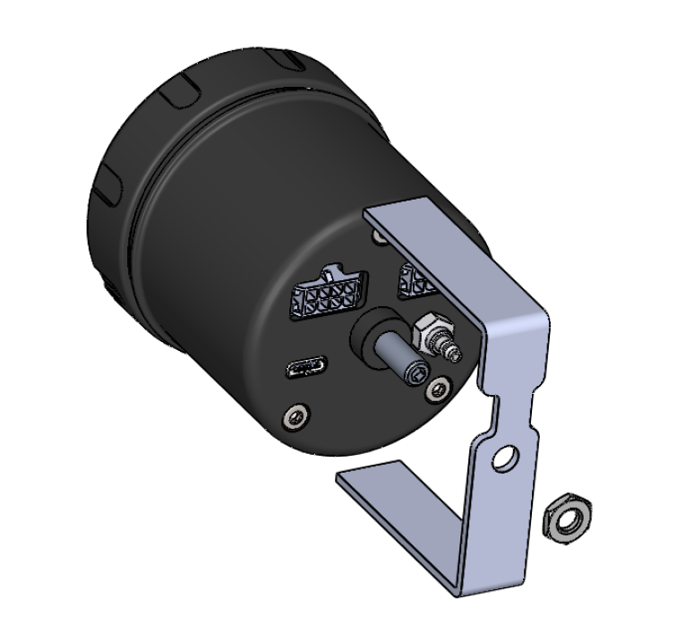
Mounting the eBoost 3
- The e-Boost3 is not waterproof and must be mounted inside the cabin. The unit has an operating temperature range of -20degC to +70degC.
- The e-Boost3 is designed to be panel mounted with the bracket supplied. Alternatively the 60mm e-Boost3 can be mounted using the Turbosmart 60mm dash mounting accessory, pod or “A pillar” mounts. The Turbosmart dash mounting accessory offers full tilt and swivel adjustment.
• The E-Boost 3 requires a vacuum/pressure signal from the intake manifold to function. A combination of poly tube and silicone hose is used to connect the E-boost 3 to a adequate vacuum/pressure signal. Route the poly tube from the E-boost 3 head unit through the fire wall approximately 100mm (4”) only as the poly tube is not rated to the high temperatures of the engine bay.
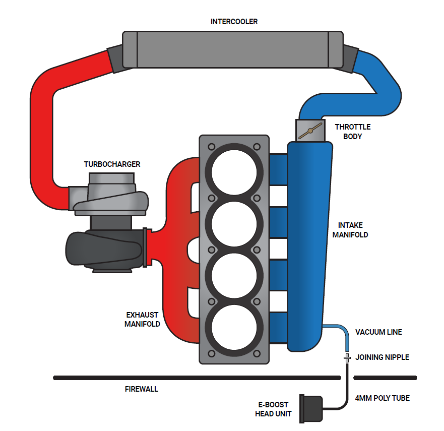
- Use the connecting barb to join the poly tube to the 3mm ID silicon hose at the firewall/bulkhead. Ensure the poly tube is pressed all the way onto the connecting barb
- Route the silicon hose through the engine bay and connect it to a pressure/vacuum signal from the inlet manifold. Use the supplied tee piece if necessary.
- Secure all connections with the supplied hose clamps
Wiring the eBoost 3
- The e-Boost3 must be connected to a typical automotive 12 volt negative earth electrical system.
- Soldering or Crimp on electrical connectors must be used on all electrical connections
- Unused wires must be insulated with electrical heat shrink or electrical tape so that they do not touch other wires or the chassis
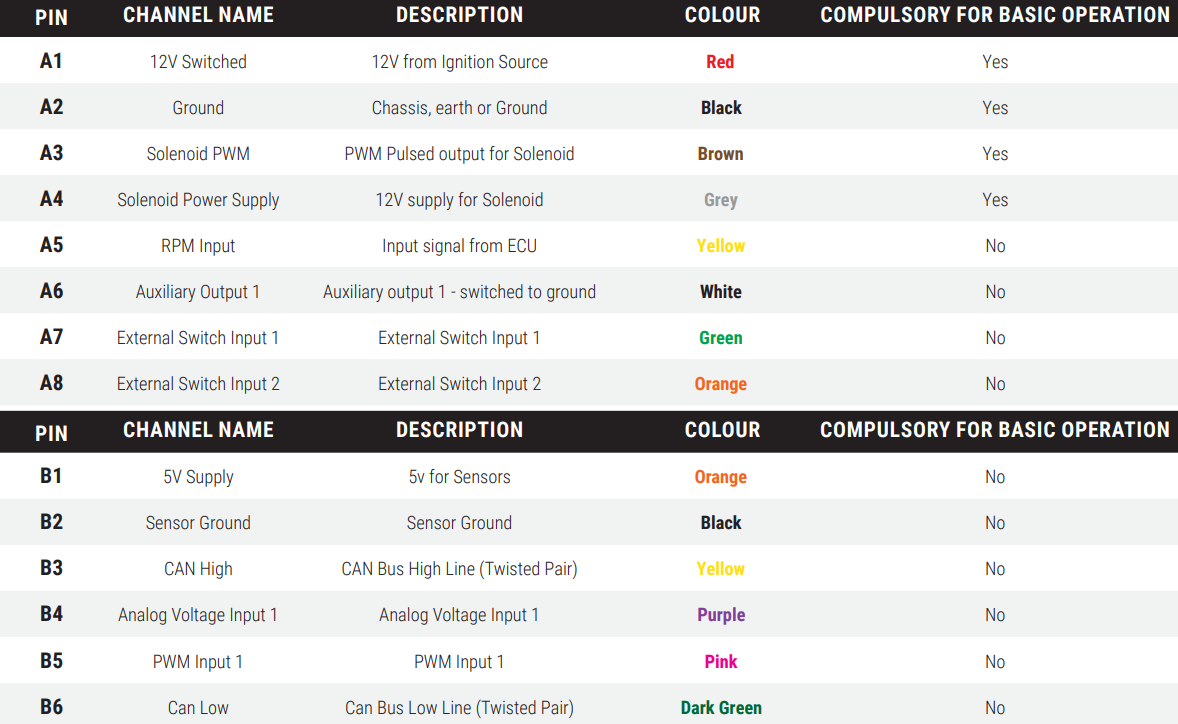
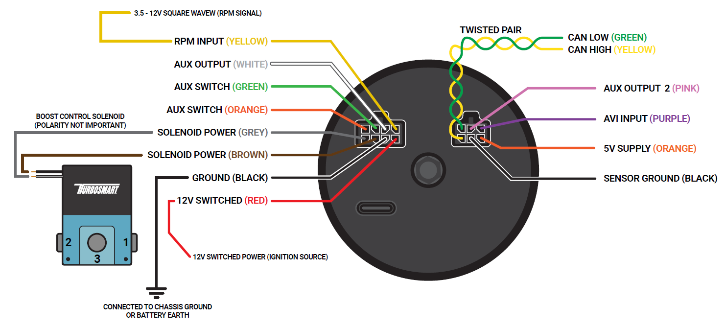
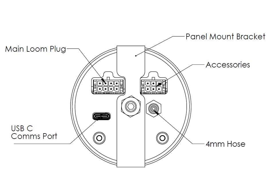
- Refer to the following table and diagram for detail on wiring the e-Boost3.
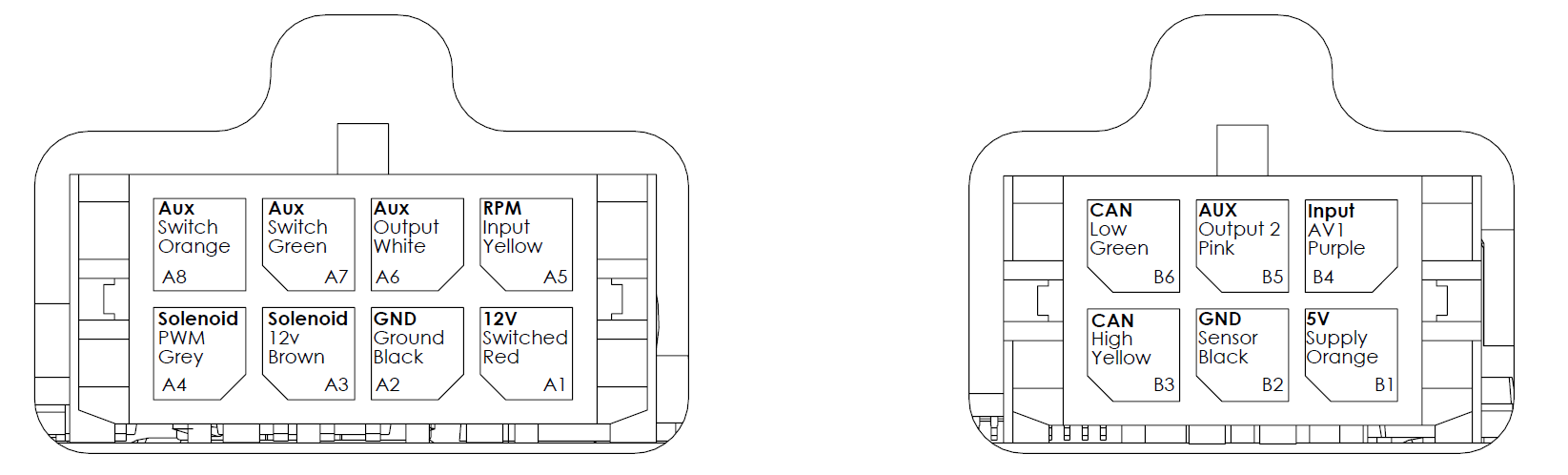
Viewed from back of eBoost.
CAN Bus expansion coming soon.
Installing eBoost 3 Solenoid
- The e-Boost3 solenoid is rated to a maximum temperature of 100 degrees Celsius (212 degrees Fahrenheit), ensure that it is mounted a minimum of 250mm (10 Inches) away from the heat of the turbo or exhaust manifold, otherwise heat shielding maybe required.
- The eB3 is supplied with a 12.7W solenoid, with the benefit of faster reaction times over the 5.4W solenoid. However both are appropriate for use and must be review to ensure similar operation on the dyno.
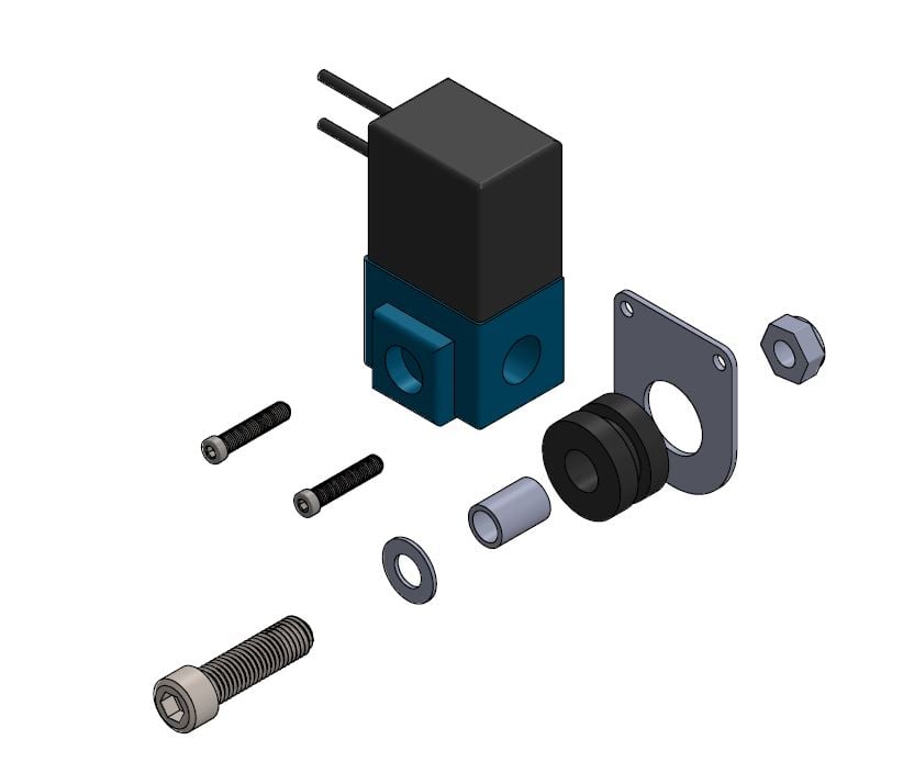
- Mount the e-Boost3 solenoid in an appropriate position in the engine bay with the mounting kit supplied.
- Fit the rubber grommet inside the mounting plate. Slide the sleeve inside the grommet. Use the M3 screws to bolt the solenoid to the mounting bracket – Note use loctite on the threads to secure. Use the M6 screw, washer and Nyloc nut to mount in a suitable location in the engine bay.
- The e-Boost3 head unit is capable of controlling two solenoids. The use of twin solenoids is not necessary but is recommended in twin turbo setups on V configuration engines as this reduces the length of hose required for plumbing which aids in response and control of the wastegates.
- The solenoid must be connected to a pressure only source which must be located before the intercooler, ideally off the compressor cover of the turbocharger. The air temperature before the intercooler is less affected by ambient conditions which will give you more consistent boost control.
INTERNAL WASTEGATE CONNECTION
WARNING! Changing to different connection methods can cause a higher than expected increase in boost pressure. Turbosmart recommends adjusting your boost controller back to its minimum setting and measuring the new minimum boost pressure achieved by the new setup before increasing your boost again.
Note: If your vehicle is fitted with a factory boost control solenoid, the hoses that run from the solenoid to the pressure source and to the wastegate actuator must be disconnected from the solenoid. Leave the solenoid plugged into the wiring loom so that the ECU is not affected.
Most factory turbocharged vehicles use an internal wastegate system to control boost pressure. The e-Boost3 controls boost pressure by controlling the pressure signal that the wastegate actuator receives from the turbocharger.
Please note that the e-Boost3 cannot be used to obtain a boost pressure lower than the standard wastegate actuators' pressure setting.
• Some factory hoses have a small restrictor fitted inside them, if the factory hoses are reused over boosting or boost spiking may occur.
• Secure all connections with hose clamps.
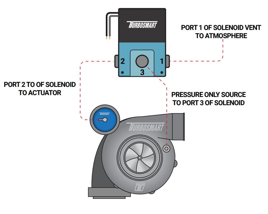
Single solenoid, single turbocharger hook up
Basic Single Internal Wastegate Setup
Port 1: vents pressure from the solenoid.
- Connect this hose to the intake side of the turbo, between the air cleaner and the inlet of the turbocharger. Otherwise connect a short piece of the silicon hose and face the vent downwards to stop water or debris entering the solenoid.
Port 2: to the internal wastegate actuator
Port 3: to pressure only source
If you are unable to achieve your desired boost pressure, it is normally due to exhaust manifold back pressure forcing the internal wastegate to open. To increase your boost pressure further, fit a higher pressure wastegate actuator to increase your minimum boost pressure.
WARNING! Fitting a higher pressure wastegate actuator may cause a higher than expected increase in boost pressure.
Turbosmart recommends resetting the boost set point values to Zero and measure the new minimum boost pressure before increasing your boost set point values.
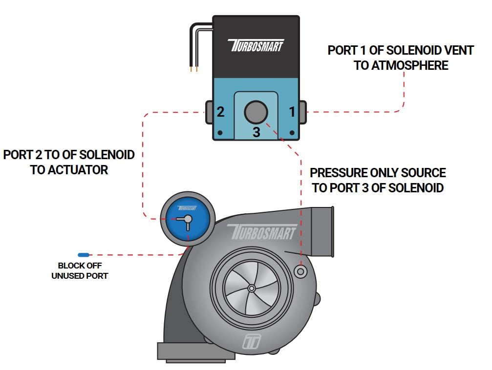
Internal wastegates with 2 ports
Port 1: vents pressure from the solenoid.
Port 2: connect to one of the ports of the actuator
Port 3: to pressure only source
• Block off unused port on the actuator with suitable blank
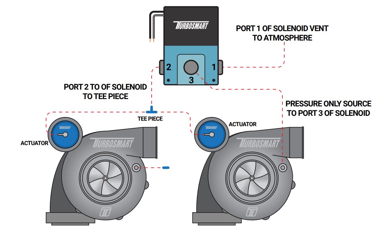
Single solenoid, twin parallel turbocharger hook up
For straight configuration twin parallel turbocharger engines E.g. RB26DETT
• The e-Boost3 is capable of controlling twin internal wastegate turbochargers with a single solenoid.
• This method is used when the turbochargers are mounted close to each other allowing the solenoid to be mounted close to both actuators
• Each solenoid port is connected as follows:
Port 1: vents pressure from the solenoid. Connect this hose to the intake side of the turbo, between the air cleaner and the inlet of the turbocharger. Otherwise connect a short piece of the silicon hose and face the vent downwards to stop water or debris entering the solenoid.
Port 2: to tee piece that feeds both actuators
Port 3: to pressure only source
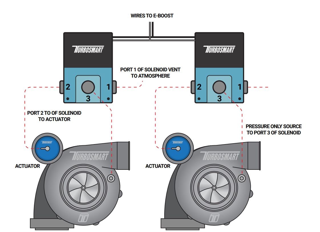
Twin solenoid, twin parallel turbocharger hook up
(For V configuration twin parallel turbocharger engines E.g. V6, V8 etc)
• The e-Boost3 is capable of controlling two solenoids for twin parallel turbocharger setups.
• This method is used when there is a great distance between the wastegates. This allows the solenoids to be mounted close to the wastegates to minimise the length of hose used and to maximise response
• You will need a second solenoid for this method (TS-0301-3007) (12.7W Solenoid)
• Connect the grey wire from the e-Boost wiring loom to one of the wire from each solenoid.
• Connect the brown wire from the e-Boost wiring loom to the remaining wire from each solenoid.
• Each solenoid port is connected as follows:
Port 1: vents pressure from the solenoid. Connect this hose to the intake side of the turbo, between the air cleaner and the inlet of the turbocharger. Otherwise connect a short piece of the silicon hose and face the vent downwards to stop water or debris entering the solenoid.
Port 2: to the internal wastegate actuator
Port 3: to pressure only source
EXTERNAL WASTEGATE CONNECTION
The first method of installation is a one port connection. If the desired boost level is not achieved i.e. boost level is too low, or not controllable, it is recommended that the wastegate spring be changed to a spring which is closer to the desired boost pressure or to trial a 2 port connection method.
There are 3 different 2 port connection methods that can be trialled to achieve different results. The 2 port method (1) can be used if there is high exhaust manifold back pressure forcing the valve open. The 2 port method (2) allows the user to achieve the maximum boost pressure their turbo system is capable of. If a wide range of boost pressures is desired i.e. 5 – 40 PSI, the 2 port method (3) with a 4 port solenoid (sold separately – TS-0301-2003) might be needed.
A single solenoid can be used to control twin wastegates in a twin turbo setup but it is recommended that twin solenoids are used in twin turbo setups to reduce the length of the pressure hoses to aid in control and response of the wastegates.
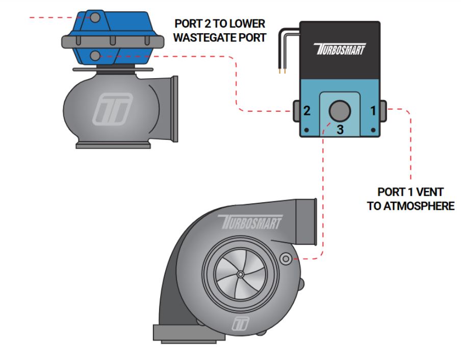
Single port, single solenoid, single turbo connection Method
Basic Single Wastegate Setup
Port 1 of solenoid vent to atmosphere
Port 2 of solenoid to bottom port of wastegate
Port 3 of solenoid to Pressure only source
Single port, single solenoid, twin turbo connection Method
(For straight configuration twin parallel turbocharger engines E.g. RB26DETT)
Port 1 of solenoid vent to atmosphere
Port 2 of solenoid to bottom port of wastegate
Port 3 of solenoid to Pressure only source
• Block off other turbocharger pressure port (if needed)
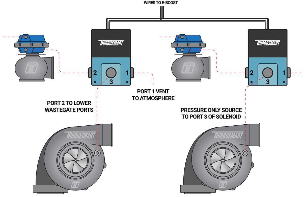
Single port, twin solenoid, twin turbo connection Method
(For V configuration twin parallel turbocharger engines E.g. V6, V8 etc)
Port 1 of solenoid vent to atmosphere
Port 2 of solenoid to bottom port of wastegate
Port 3 of solenoid to Pressure only source
• Join the wires from both solenoids together (polarity not important) and then connect them to the brown and grey wires of the wiring loom
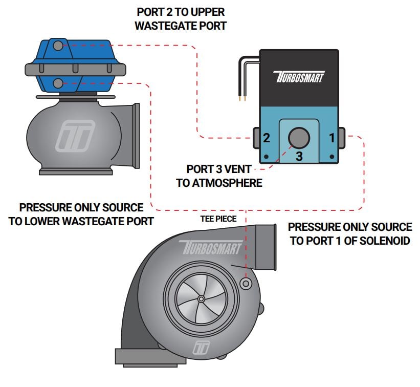
Two port, single solenoid, single turbo connection Method
(For controlling boost on a single turbo, single wastegate, single solenoid turbo system with high back pressure)
NOTE: An increase in your minimum boost pressure is expected when using any of the 2 port connection methods. Ensure all boost set point values and gate pressure values are set to Zero and measure the new minimum boost pressure achieved by this method before increasing your Boost Set Point values.
Port 1 is connect the bottom port of the wastegate and a Pressure only source via a tee piece
Port 2 of the solenoid to the top port of the wastegate
Port 3 of solenoid vent to atmosphere
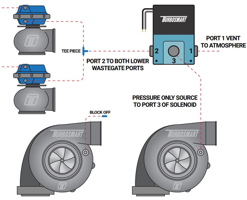
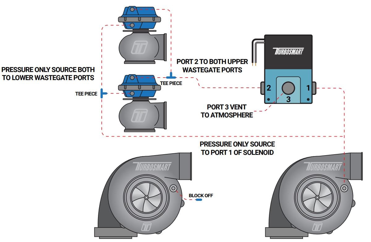
Two port, single solenoid, twin turbo connection Method
(For controlling boost on a twin turbo, twin wastegate, single solenoid turbo system, on a straight configuration engine with high back pressure)
Port 1: Connect the bottom port of the wastegates and Port 1 of the solenoid to a Pressure only source via tee pieces
Port 2: of the solenoid to the top port of the wastegates via tee pieces
Port 3: of solenoid vent to atmosphere
• Block off other turbocharger pressure port (if needed)
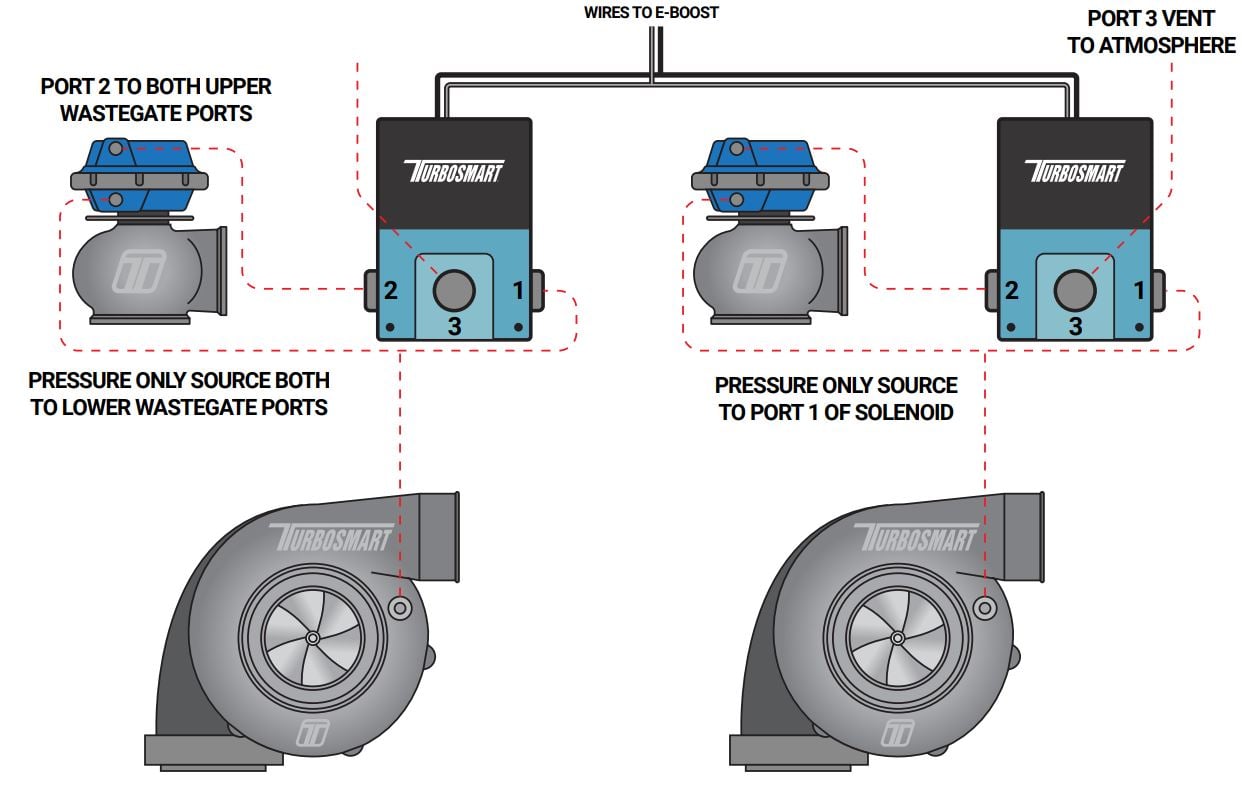
Two port, twin solenoid, twin turbo connection Method
(For controlling boost on a twin turbo, twin wastegate, twin solenoid turbo system, on a V configuration engine with high back pressure)
Port 1: Connect the bottom port of the wastegate and Port 1 of the solenoid to a Pressure only source via a tee piece
Port 2: of the solenoid to the top port of the wastegate
Port 3: of solenoid vent to atmosphere
• Join the wires from both solenoids together (polarity not important) and then connect them to the brown and grey wires of the wiring loom
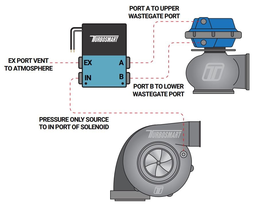
Two port, single 4 port solenoid, single turbo connection Method
(For obtaining a wide range of boost pressures e.g. 5 – 40 PSI. This connection method has varying degrees of success depending on turbo system)
Port A of solenoid to Top port of wastegate
Port B of solenoid to Bottom port of wastegate
EX port of solenoid vent to atmosphere
IN port of solenoid to Pressure only source
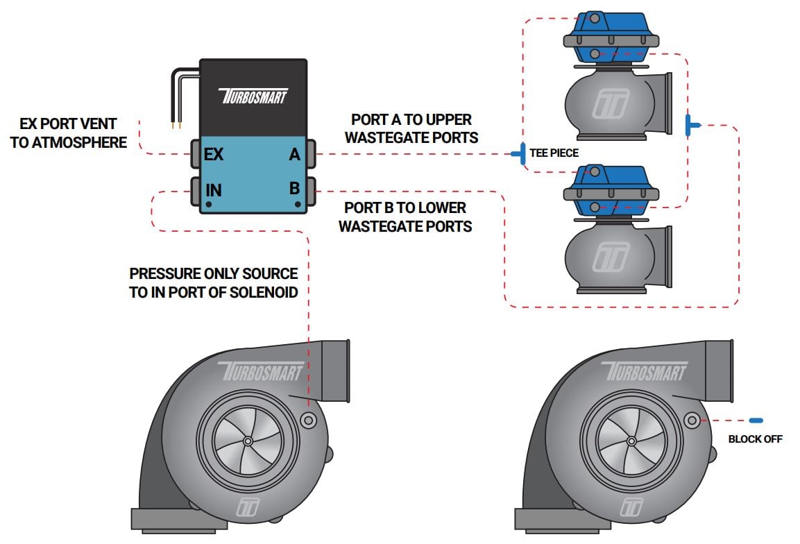
Two port, single 4 port solenoid, twin turbo connection Method
Port A of solenoid to Top port of wastegates
Port B of solenoid to Bottom port of wastegates
EX port of solenoid vent to atmosphere
IN port of solenoid to Pressure only source
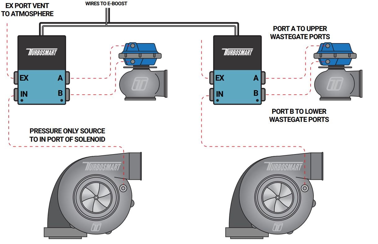
Two port, twin 4 port solenoid, twin turbo connection Method
Port A of solenoid to Top port of wastegates
Port B of solenoid to Bottom port of wastegates
EX port of solenoid vent to atmosphere
IN port of solenoid to Pressure only source
- Join the wires from both solenoids together (polarity not important) and then connect them to the brown and grey wires of the wiring loom
Basic Operation
 |  |  |
The e-boost3 is turned on by switching on your ignition.
Turning off the e-Boost3: The e-Boost3 is turned off by turning off your ignition.
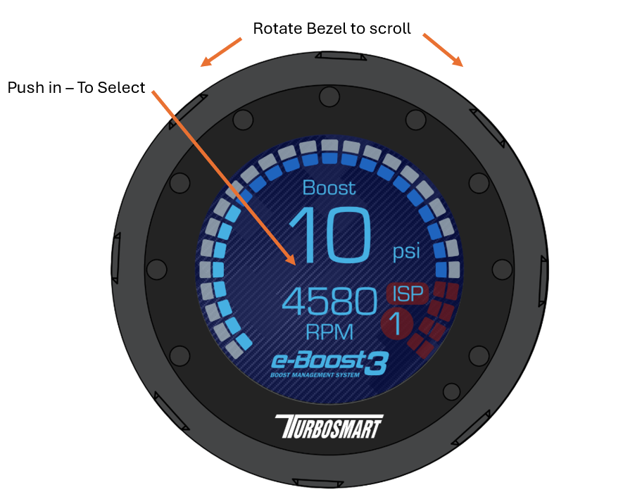
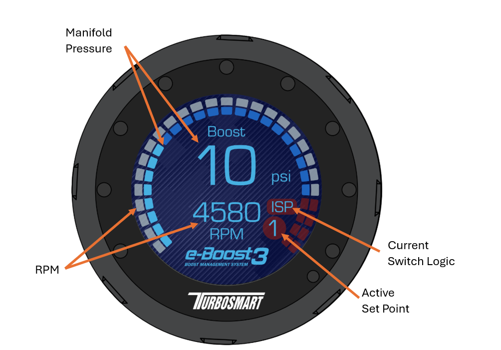
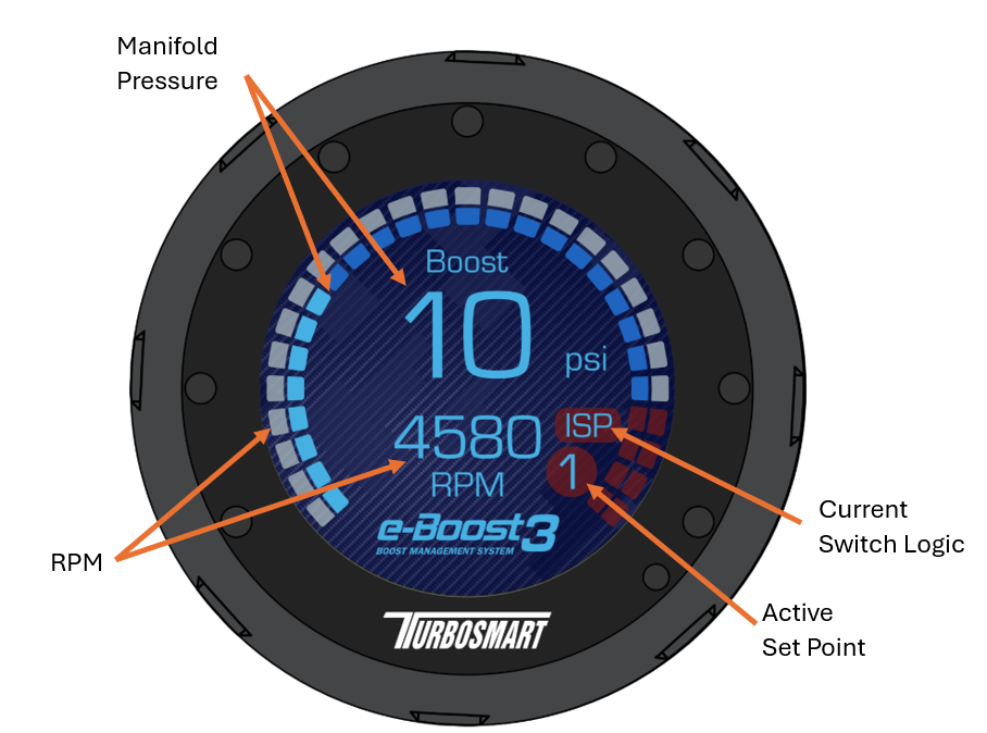
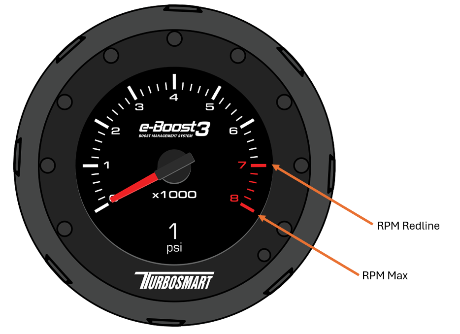
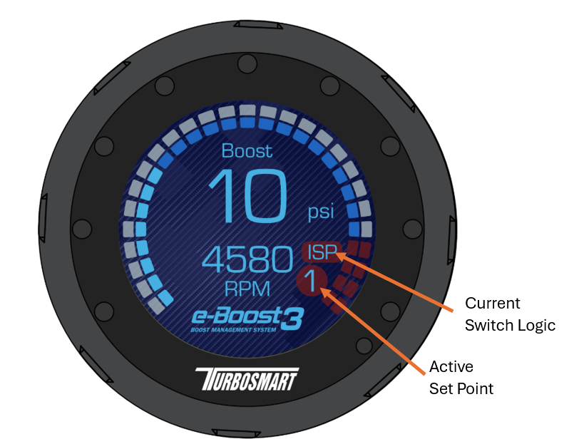
Live Mode: When the e-Boost3 is turned on, it automatically goes into live mode and displays the current vacuum/boost on boost Gauge 1 (Pictured above)
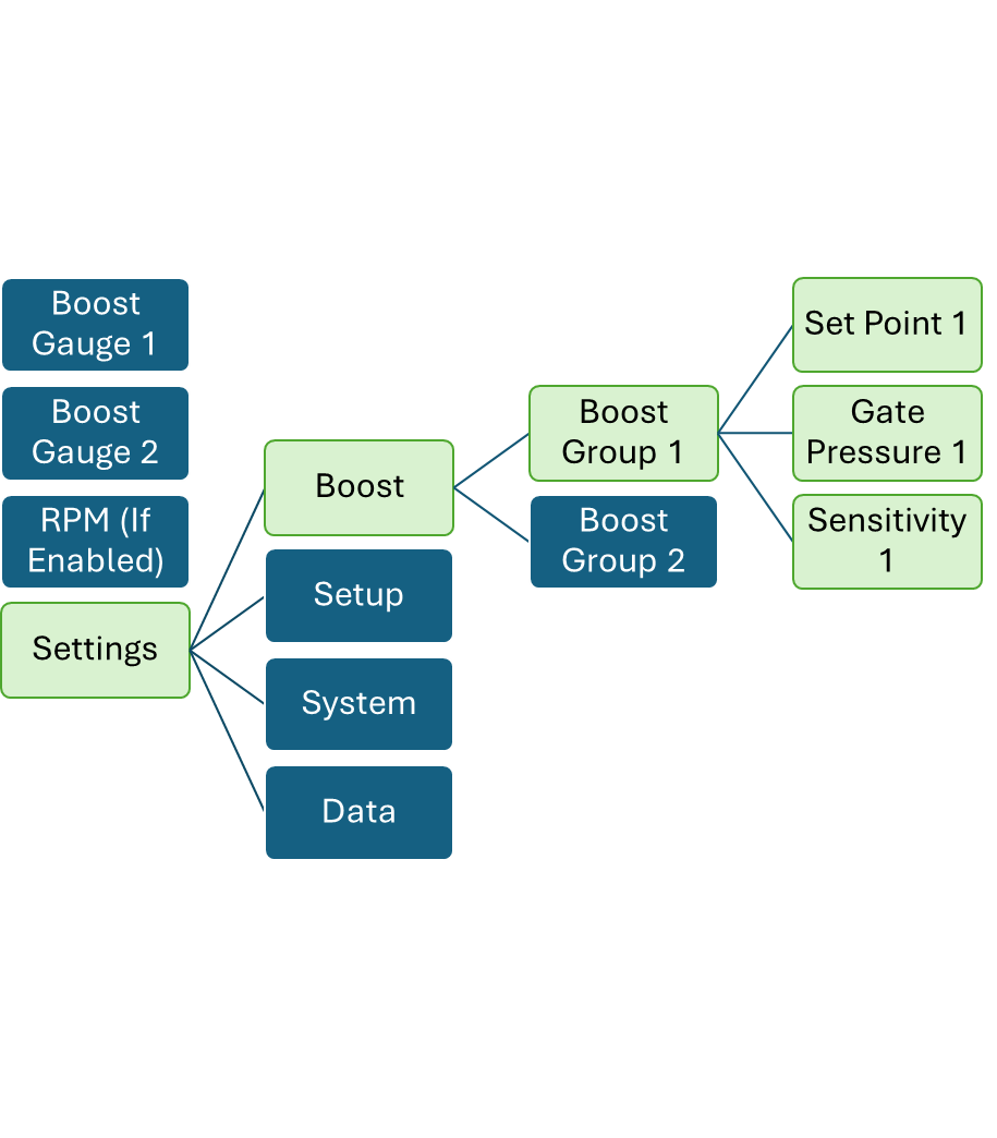
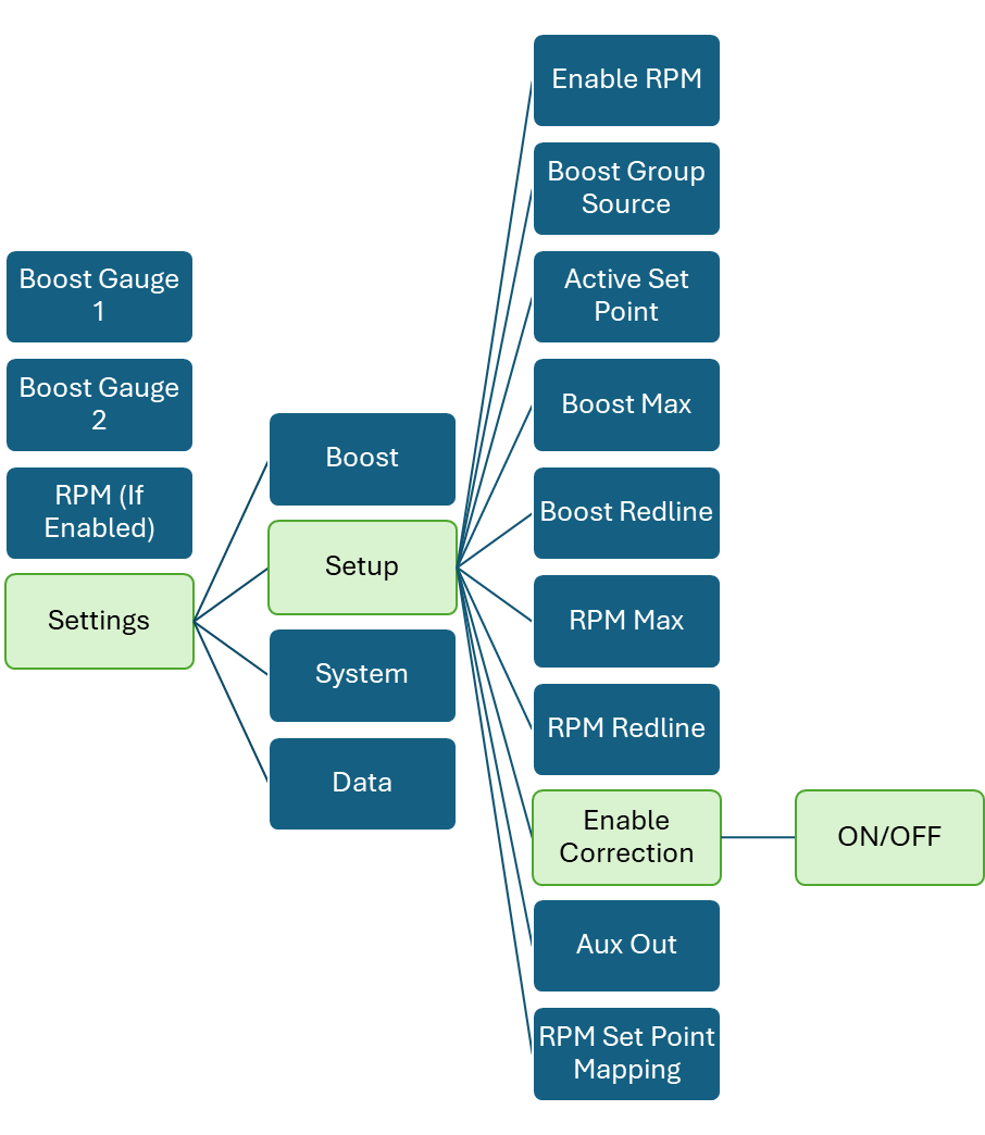
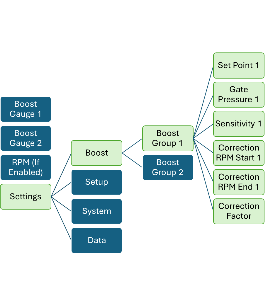
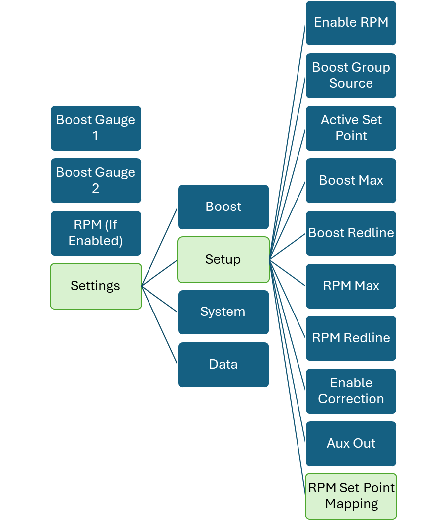
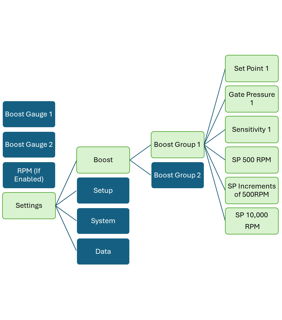
Boost Setup Menu: To enter the boost setup menu, in live mode, Rotate to Settings select Boost and the relevant Boost Group for editing.
Settings Menu: To enter the settings menu, in live mode, rotate to the settings menu.
Navigation and adjusting values in menus: To navigate and adjust is done by rotating the rotating bezel.
Entering menus: Entering menus can be done by pushing in and exiting by long pressing out.
Saving settings: Short Press when values are highlighted red.
Exiting menus: When in any menu, HOLDING the Push in will bring you back to the previous page.
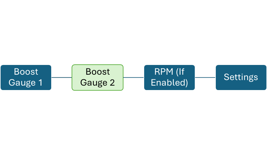
Live Menu Mode
When the e-Boost3 is powered up, the display will automatically go into Boost Gauge 1. Rotating Clockwise One Detent will scroll through the live mode menu.
Main Boost Gauge: Live boost is the default display and will display live boost or vacuum readings.
- Set Point: Shows the current set point value the unit is set to. Pushing in and rotating changes the value
- Boost Gauge settings are determined in the settings.
- RPM will only be active if enabled in settings.
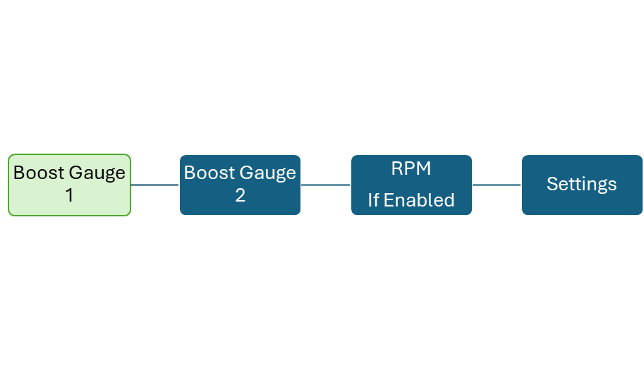
Secondary Boost Gauge: Live boost is the default display and will display live boost or vacuum readings. Max boost is recorded with the yellow circle
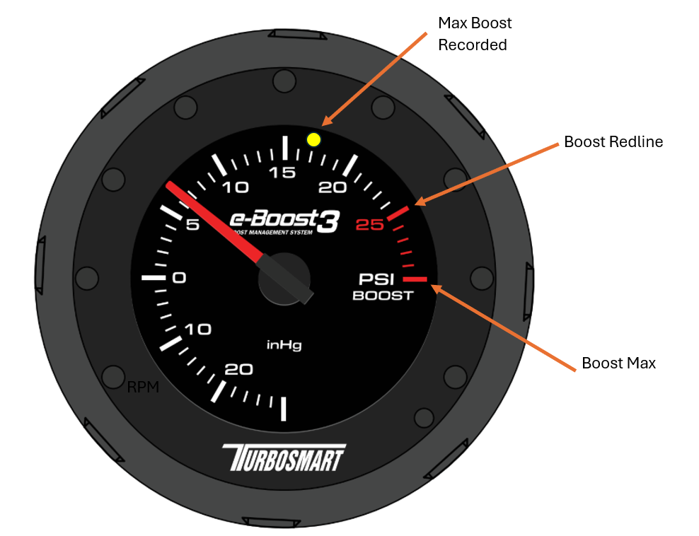
Max Boost is a recorded value that is set from the highest manifold pressure recorded on the device.
Boost Redline adjusts the value at which the redline starts from. This value must be smaller than the Boost Max.
Boost Max adjusts the final value of the graphical interface.
Boost Min adjusts the lowest value that is graphically represent.
Live RPM: Live RPM will display the current RPM of the engine. If you have not selected in settings your RPM signal then this parameter will not appear.
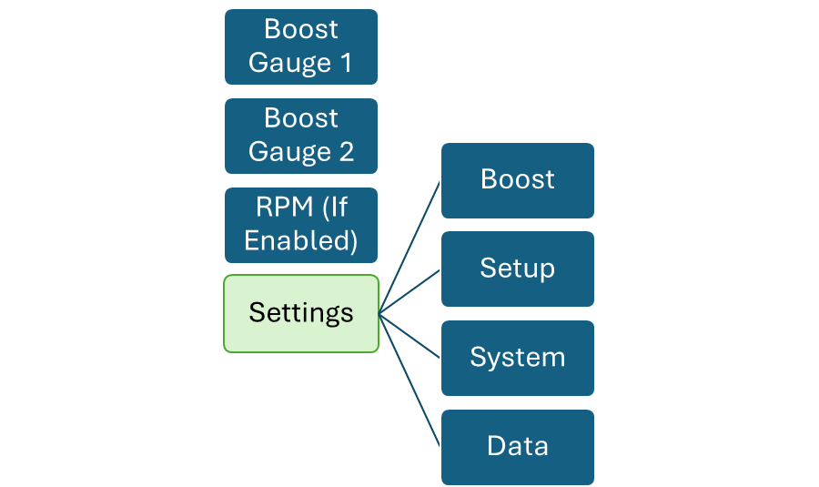
Initial Setup and Functionality
Entering setup menu
Rotating to the Settings menu is simply done by rotating clockwise till the settings appears on the screen.
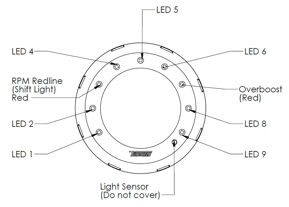
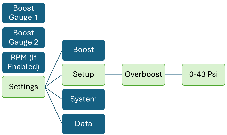
Overboost shutdown
THIS MUST BE SET UP FIRST OR YOUR ENGINE WILL NOT PRODUCE ANY BOOST OVER 7PSI
To enter the overboost rotate to the settings menu
Turbosmart requires that this function is used together with another form of over-boost protection, such as an ECU-controlled fuel/ignition cut or an over-boost valve. This function on its own will not prevent an over-boost event if a mechanical failure stops the e-Boost from controlling the wastegate, or if incorrect wiring causes electromagnetic interference to the e-Boost.
If the Over boost is triggered the e-Boost3 begins to reduce the boost pressure to half of that set in the Over boost parameter. Once this safe pressure is achieved the e-Boost will return to normal operation. Over boost must be set to a level at least 2.2psi (0.15 bar or 15kPa) above the highest boost pressure. When the Over boost is triggered over boost LED will flash on the display to indicate that your boost pressure has reached the over boost shut down value. Over boost LED will continue to flash on the display until the pressure has gone into vacuum the unit will then return to normal operation. Over boost LED will flash on the screen when triggered in any state.
The Over boost is factory set to 7 psi (0.48 bar or 48 kPa), so you must enter a figure in order for the e-Boost to produce more than a standard boost pressure. The purpose of this feature is to protect your engine against accidentally entering a boost set point value that is too high, preventing a dangerously high boost pressure. Extreme care should be taken when setting this parameter. Turbosmart recommends that you seek advice from an appropriately qualified technician regarding the Over boost setting.
Pressing into the over boost menu and rotating when the value is selected red will allow changes to be made to the value. Short Press in will finalise the value.
Setting nSP (Number of Set Points)
The e-Boost3 can control up to 6 individual boost groups. Setting Number of Set Points to a value from 1-6 will then enable that number of boost groups (and their associated set point, gate pressure and sensitivity) in the boost menu and live mode.
Rotating to the Settings, setup and set points will allow the number of set points to be selected. Clicking in will allow the number to be changed, and short pressing will allow the number to be finalised.
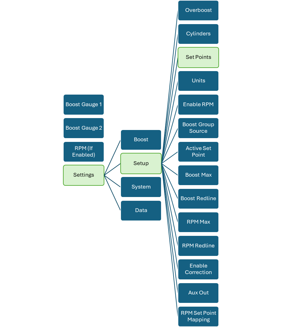
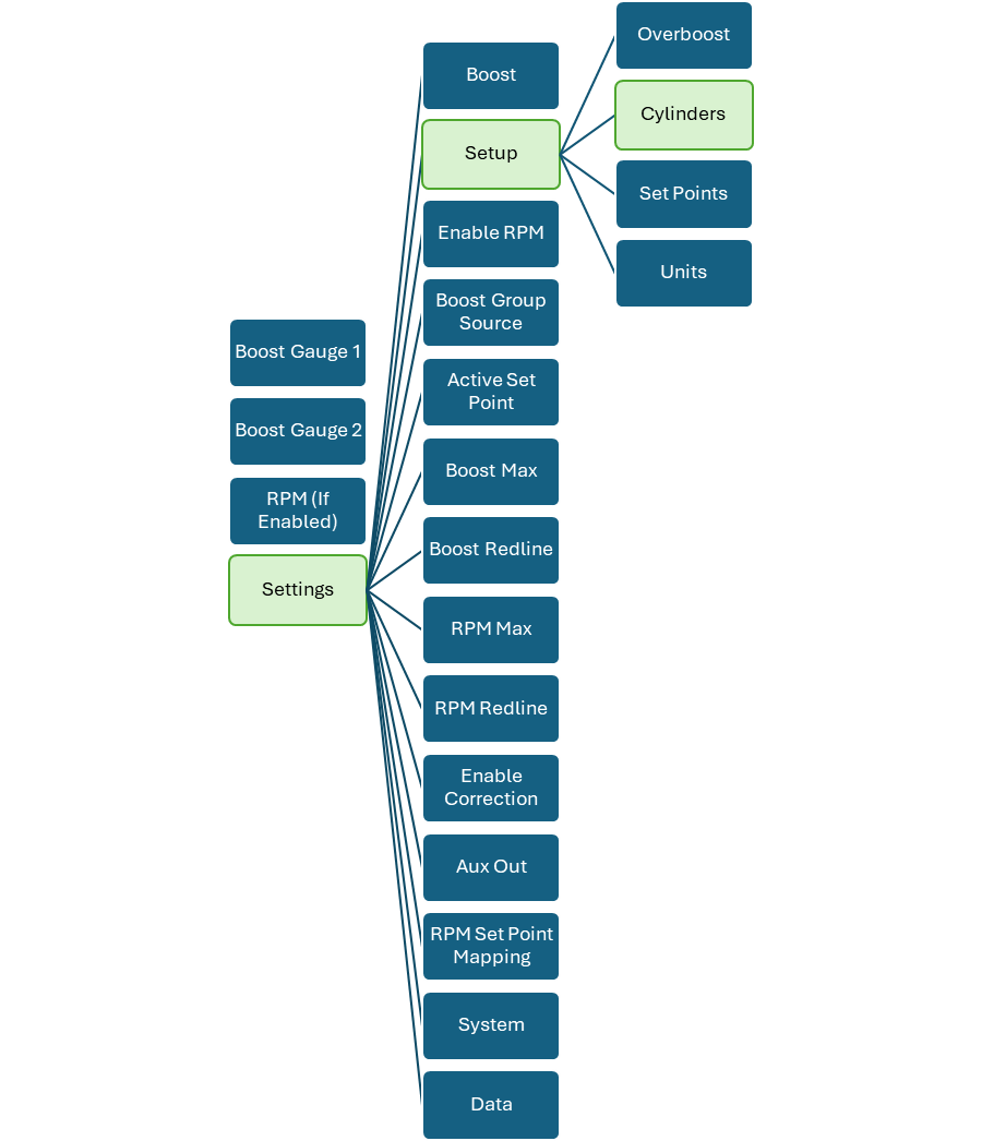
Setting Cylinder (RPM Signal Input Calibration)
If you have connected the yellow RPM wire to an RPM signal from your ECU you will need to input the number of cylinders / rotors in order to configure the RPM signal correctly i.e. the number of pulses per complete engine cycle being picked up from the RPM output of the ECU. The number of cylinders available is between 1 and 16. The RPM input can accept a square wave signal between 3.5 and 12V. Twin rotor and triple rotor engines can be configured as 4 and 6 cylinders respectively.
Rotating to the settings menu, setup and cylinders will allow the number of cylinders to be changed. Clicking in will allow changing of the number and short pressing will finalise the amount of cylinders.
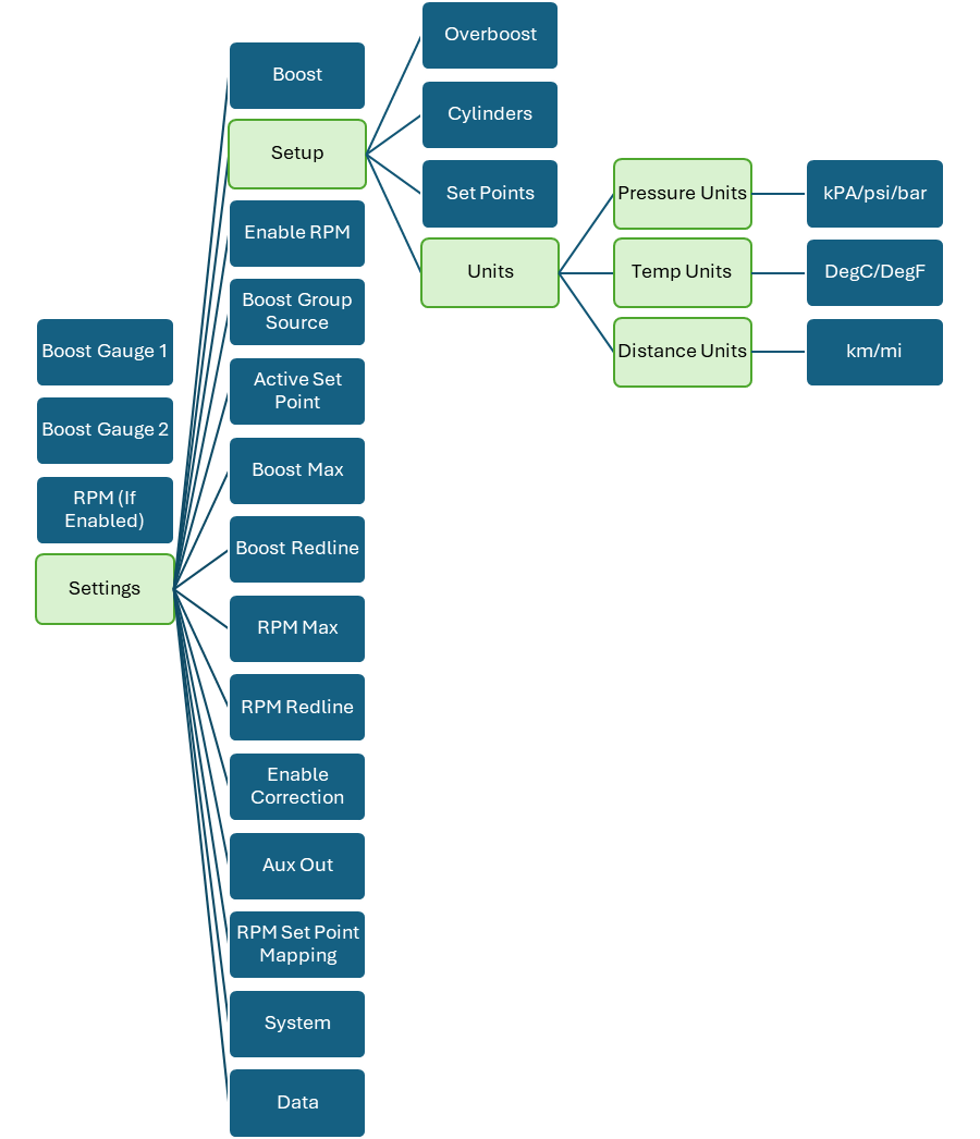
Setting Units
The e-Boost3 pressure readout can be configured in either bar, psi or kPa, the default setting is in psi. This allows you to tailor the readout to suit your own preference. Note that when the psi scale is selected and the e-Boost3 is under vacuum conditions the display will read in inches of Mercury (inHg) not negative psi. Navigate to the settings menu, setup and units. Clicking in and scrolling will allow the modification of the desired units for your application.
eBoost Requires a reboot to render these numbers.
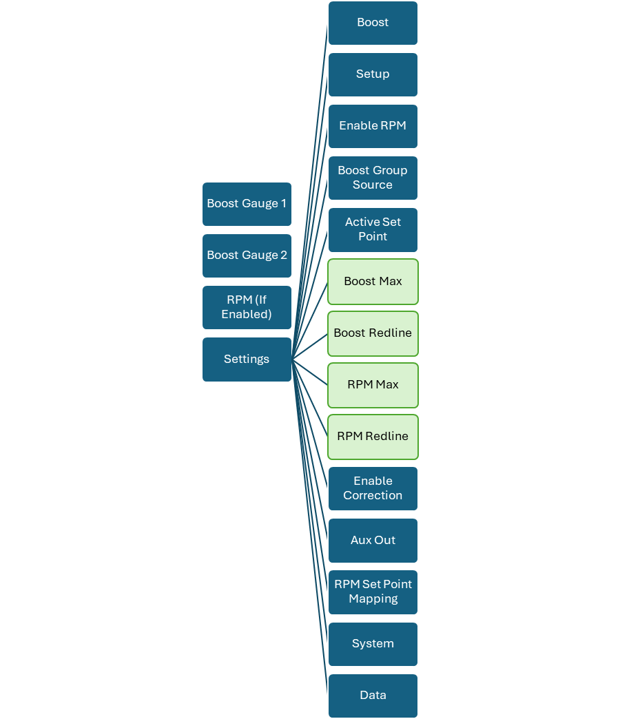
Setting Visual Boost Display Limits
Boost gauges can be rescaled depending on what is necessary for application. The Boost Redline and Boost Max.
RPM gauges also have the same ability to change the RPM Redline and the RPM Max.
Navigating to the Graphical section of the eBoost 3 is done via settings, and setup. The Boost and RPM sections are after the active set point. Numbers can be selected with a short press in and a short press out. eBoost Requires a reboot to render these numbers.
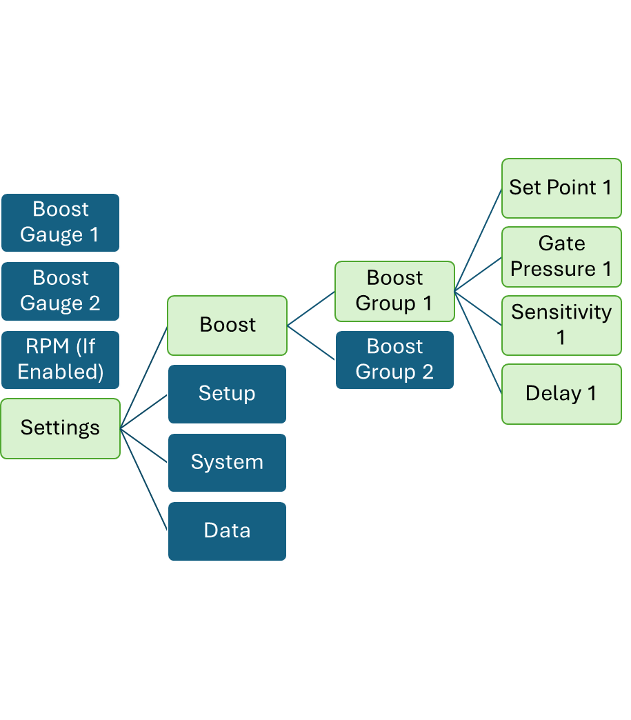
Boost Setup
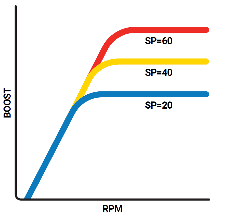
Set Point (SP)
The SP value determines the DUTY CYCLE the solenoid will operate at when the gate pressure is reached. The SP value is not the amount of boost pressure your turbo will produce. This is a value between 0 – 99. The larger the value, the more boost the turbocharger will produce. Start the setup by increasing the SP value to 20. Bring the car onto boost and see what the maximum boost pressure is. Increase the value in small increments until you achieve your desired boost pressure. The SP value can also be adjusted while the car is on boost however, instead of the SP value being displayed, the boost pressure will be displayed so you know what pressure you are achieving. This is the easiest way to set your set points.
Navigate to the relevant Boost Group and modify the settings by selecting the SP (Number) and rotating and pressing to save/exit.
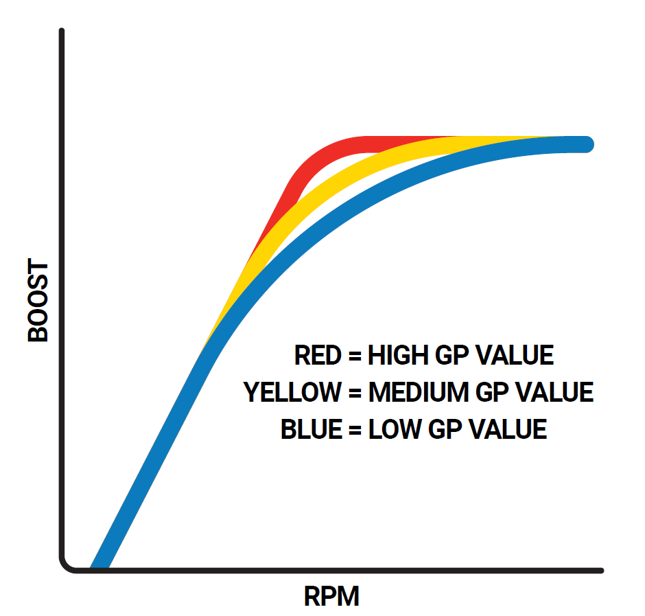
Gate Pressure (GP)
This feature helps bring boost on faster at lower rpm and will give an increase in torque. Start by setting the gate pressure 5 PSI below the desired boost pressure with the corresponding SP value e.g. if the desired boost pressure is 15 PSI, set the gate pressure to 10 PSI first and adjust from there. Adjust the value higher to increase the response of the turbocharger or decrease the value to reduce the response. If this setting is too close to target boost, you will get a boost spike.
Navigate to the relevant Boost Group and modify the settings by selecting the GP (Number) and rotating and pressing to save/exit.
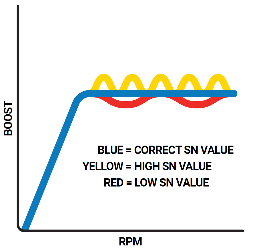
Sensitivity (SN)
The sensitivity is how sensitive the e-Boost 3 is to changes in the boost curve. Tuning should start at 0 and if the curve looks slow to get to a stable pressure, increase the sensitivity. With straight gates, no more than 20% should work and poppet style can be up to 40% dependent on if there is oscillation or not. Note a sensitivity of 0 means that the duty cycle will not change regardless of the rate of change in pressure and will effectively work like a manual bleed valve.
Navigate to the relevant Boost Group and modify the settings by selecting the SN (Number) and rotating and pressing to save/exit.
Advanced Functionality
RPM Signal Connection (Optional)
RPM signal connection is ONLY for Tacho mode, RPM set point mapping, Boost correction, shift light function and other advanced features. Turbosmart recommends your RPM signal be connected by an appropriately qualified technician or automotive electrician. For further information consult your vehicle’s manuals or your local automotive electrician. The e-Boost3 is ONLY able to accept an RPM signal in the form of a square wave that is switching between 0V and 3.5-12 volts.
The following points should be followed to connect your RPM signal to an ECU pin.
- Locate your ECU RPM signal wire and splice into the signal wire coming from your ECU.
- Check the output you are splicing into is a square wave that is switching between switching between 0V and 3.5-12 volts with an appropriate meter.
- Connect the yellow RPM wire from the e-Boost to the spliced section of the ECU RPM out.
- Turn on the e-Boost3 and configure your signal to the number of cylinders or rotors your engine has using the cylinder parameter located in the setup menu.
- In live mode with your engine running press mode once to show live RPM. The display should be reading RPM. If the display is not reading correctly re-check the cylinder configuration in the setup menu.
- Note: If the OEM tachometer does not display RPM after installing the E-Boost 3, a 2 ohm or higher resistor needs to be installed in line between the ECU RPM output pin and the E-Boost 3.
Switch Logic
The e-Boost3 is capable of 9 different methods of boost switching.
IMPORTANT! Before setting up your boost group switching you should know what boost pressure you achieve with each set-point setting in its relevant boost group. For example if you want to run four different boost levels you should set up four groups and test what each of your boost levels are before setting up switching between each boost group.
ISP (Internal switching point): Switching between boost groups is achieved by pushing in and rotating the bezel to select the current boost group. Pushing in, will select that boost group.
ESP (External switching point): Up to 4 boost groups can be selected directly by externally grounding or earthing the green and/or orange wires from the e-Boost3 loom to the chassis. The appropriate wire corresponding to the set point you wish to select is shown in the table below.
Active Set Point | Green Wire | Orange Wire |
Set Point 1 | Not Connected | Not Connected |
Set Point 2 | 0V Grounded | Not Connected |
Set Point 3 | Not Connected | 0V Grounded |
Set Point 4 | 0V Grounded | 0V Grounded |
BOD (Boost on demand): Allows you to select a boost set point for an inputted value of time before returning to the previous set point. When the BOD function is activated within the switch logic menu, an additional sub-menu will appear in bG2 and bG3 of the boost menu called bd2 and bd3. bd2 is the value of time in seconds, bG2 will be selected before returning to the previous set point. Bd3 is the value of time in seconds, bG3 will be selected before returning to the previous set point.
- Earthing the green wire will trigger bG2 for the inputted value of time
- Earthing the orange wire will trigger bG3 for the inputted value of time
- Maximum time that a boost group can be selected is 99 seconds
- The boost and setup buttons on the e-Boost3 unit will function as normal in ISP mode.
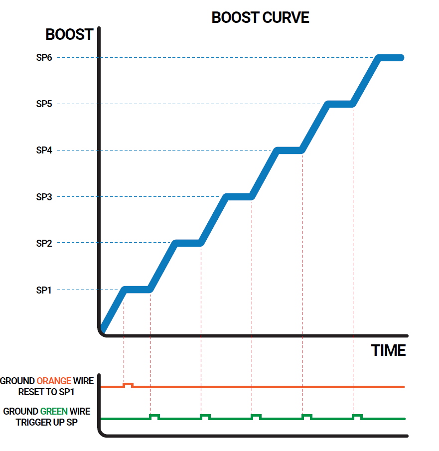
Sequential Switching Function A
Allows you to sequentially switch between different boost settings. This switch logic could be applied in a situation where you want to have a different boost level in each gear.
- Earthing the green wire with a switch will scroll up a single set point.
- Earthing the green wire again will switch up another single set point.
- The maximum number of set points that can be switch up to is determined by nSP in the setup menu.
- Once the maximum set point is reached through switching further switching not increase the set point any higher.
- Earthing orange wire with a switch will reset and return to SP1.
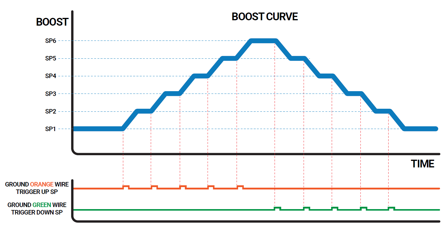
Sequential Switching Function B
Sequential Switching Function B allows you to sequentially switch up and down between different boost settings using external switches. This switch logic could be applied in a situation where you want to have a different boost levels in each gear.
- Earthing the green wire with a switch will switch up a single set point.
- Earthing the green wire again will switch up another single set point.
- The maximum number of set points that can be switch up to is determined by nSP in the setup menu.
- Once the maximum set point is reached through switching (note: will only switch up to SP6).
- Earthing orange with a switch will wire switch down a single set point.
- Earthing the orange wire again will down another set point. (note: will only switch down to SP1).
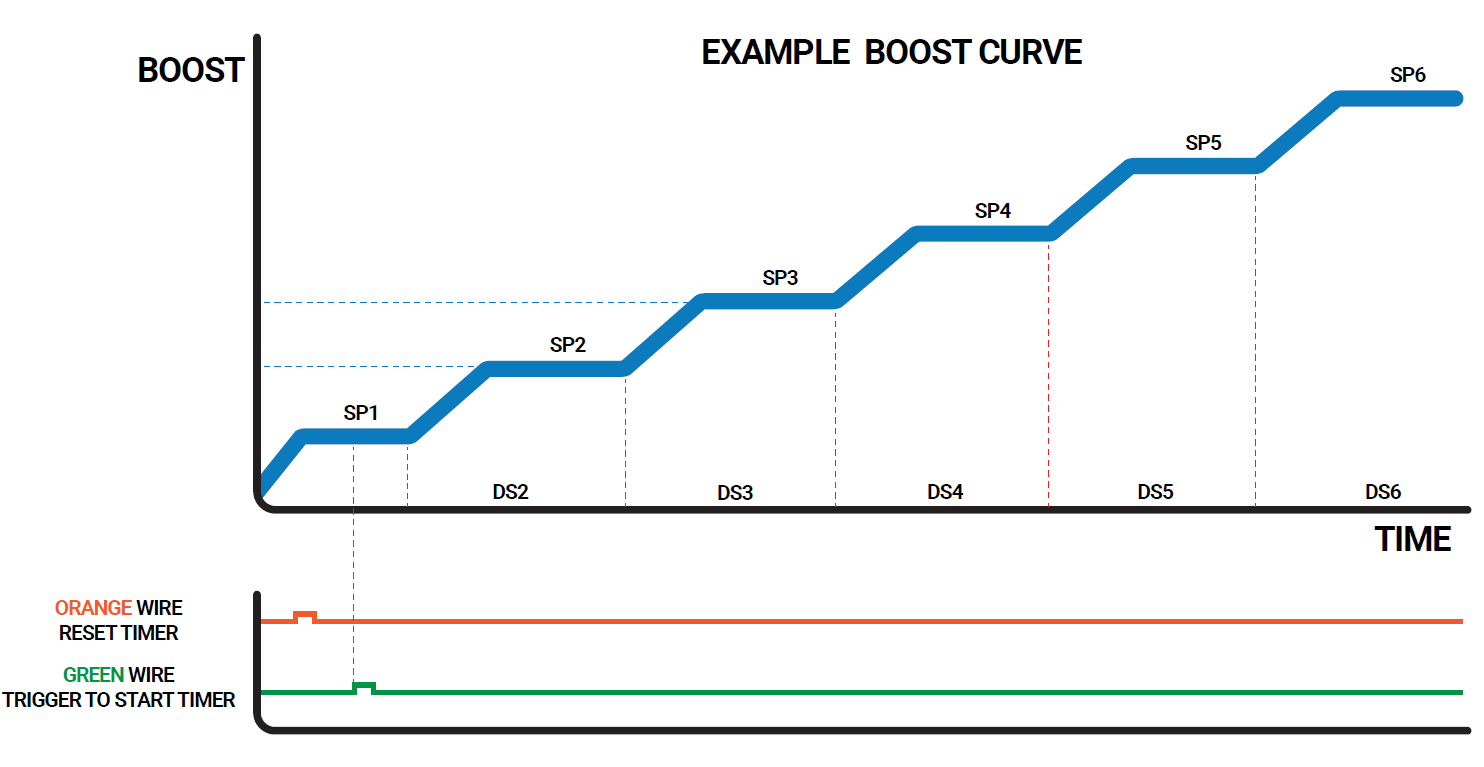
Sequential Switching Function C
Timed sequential switching function C allows the boost groups/set-points to be active then switched at predetermined time intervals. This switch logic could be applied in a drag racing situation where you want to switch boost levels at known time intervals within your elapsed time (ET).
- With SSC active dS1-dS6 will appear in each boost group.
- These time intervals can be entered as the amount of time you want each set point to be active before switching to the next set point.
- Time delays are in increments of 1/10th of a second, with the maximum allowable being 99 seconds.
- dS1 will refer to the amount of time SP1 is active before switching to SP2, dS2 to the amount of time SP2 is active before switching to SP3 and so on.
- Earthing the orange wire with a switch will reset the timer and switch to SP1/BG1.
- Earthing the green wire will start the timer and the time interval dS1 during which SP1 will be active.
- At the end of the time interval dS1 the unit will switch to SP2 and SP2 will be active for the time interval dS2.
- The same procedure will happen for all active set points (determined by the nSP parameter in the setup menu)
- Once the last time interval has ended the unit will continue to operate at the final set point.
- Note to skip a set point/boost group set the dS parameter for that group to equal zero.
- This is a solely time based switching method and is not dependant on switching except for the reset to SP1 (earthing the orange wire) and a GO (earthing the green wire) which will start the timer.
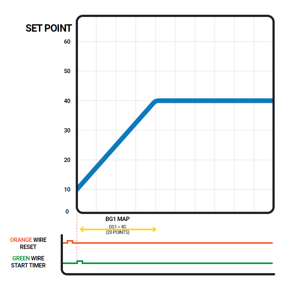
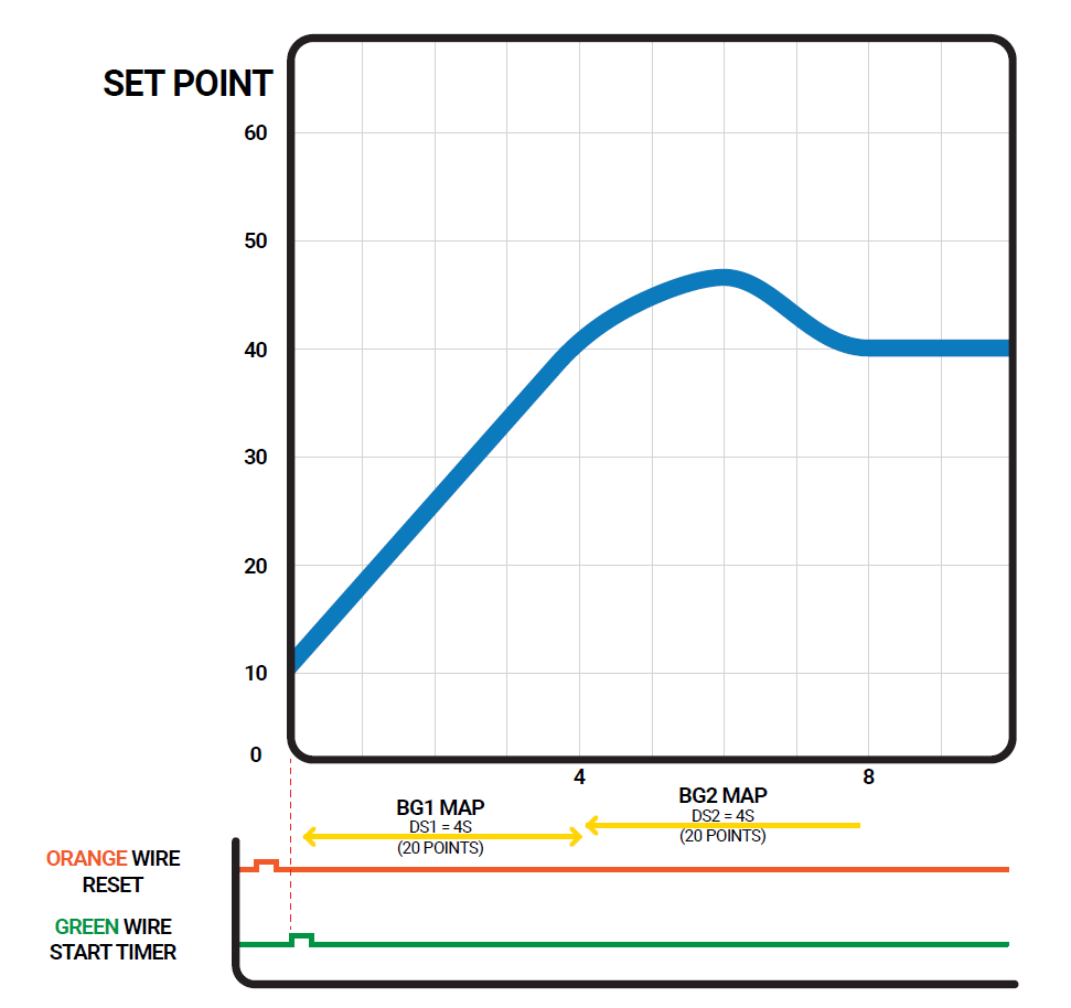
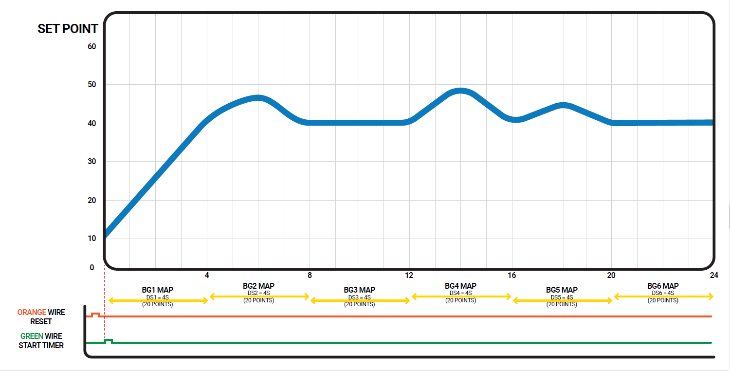
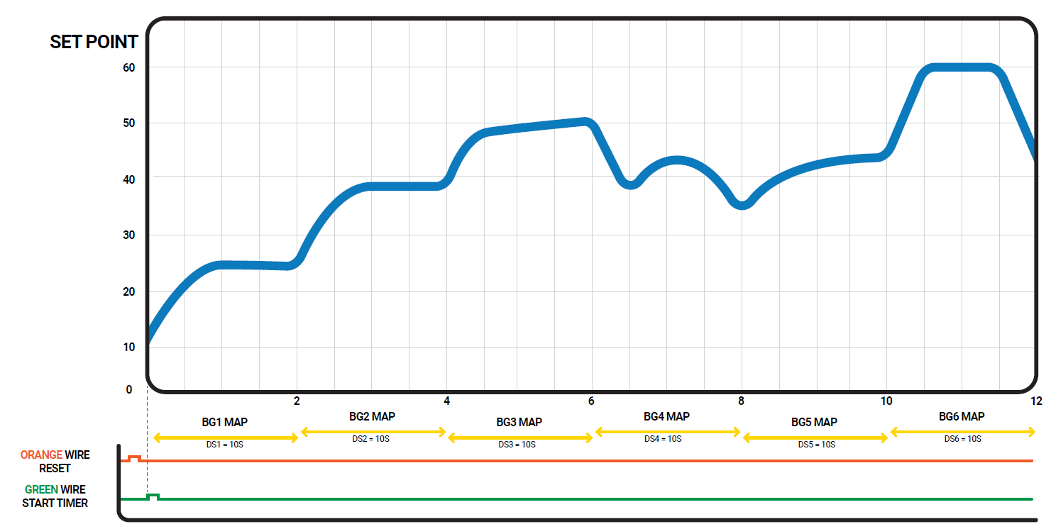
Sequential Switching Function E
Sequential switching function E Timed sequential switching function E allows the set-points to be mapped and switched during a predetermined time interval.
- dS1-6 is the amount of time you wish each boost group to be active for, up to a maximum of 99 seconds. dS can be entered in 0.1s increments – 6 seconds = 060
- Only the first 4 seconds of each boost group can be mapped and the last set point value that is mapped will continue to be active for remainder of the time delay (if set longer than 4 seconds).
- The first 4 seconds can be mapped in 0.2 second intervals which means you can have up to 20 mapped set point values within the first 4 seconds of the boost group.
- Entering a value in the SP parameter of the boost group will paste this value through all time increments.
- Gate pressure is not available with this function and will no longer be visible in the boost group.
- dS1 will refer to the amount of time BG1 is active before switching to BG2, dS2 to the amount of time BG2 is active before switching to BG3 and so on.
- This is a solely time based switching method and will not be dependant on switching except for a reset to SP1 (earthing the orange wire) and a GO (earthing the green wire) which will start the timer.
Example: dS1 = 4s with 4s map defined.
Example 2: dS1 = 4s, dS2 = 4s with 8s amp defined
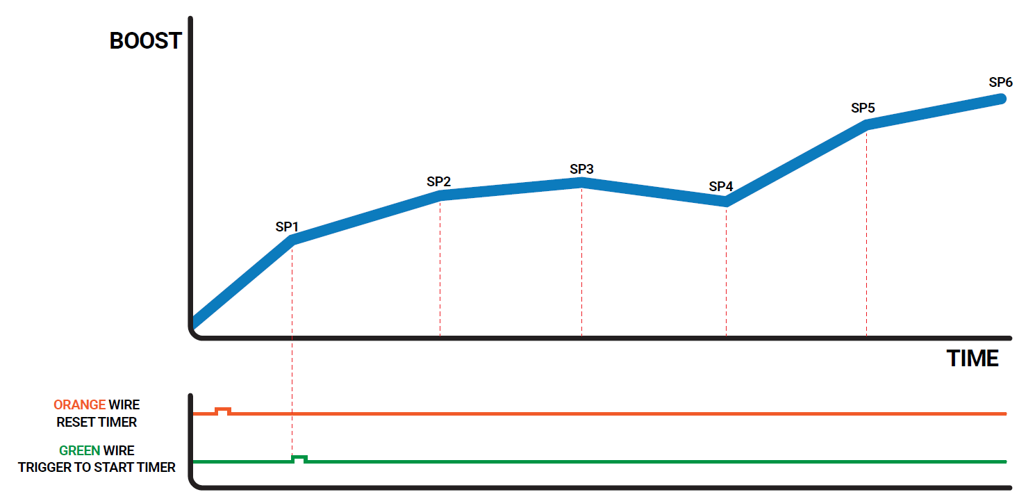
Sequential Switching Function F
Timed sequential switching function F allows the set point values to gradually increase over time. This switch logic could be applied in a drag racing situation where you want to gradually increase boost levels over a desired time interval within your elapsed time (ET). The Set point value will increase linearly between the user defined set point targets, e.g. If SP1 was 20 and SP2 was 50 and the delayed time was 5 seconds, when the timer is started, it would start at SP1 and over 5 seconds, gradually ramp up to SP2
- With SSF active dS1-dS6 will appear in each boost group.
- These time intervals can be entered as the amount of time you want each set point to be active before switching to the next set point.
- Time delays are in increments of 1/10th of a second, with the maximum allowable being 99 seconds.
- dS1 refers to the amount of time that it will take SP1 to gradually increase to SP2, dS2 refers to the amount of time that it will take SP2 to gradually increase to SP3 and so on.
- Earthing the orange wire with a switch will reset the timer and switch to SP1/BG1.
- Earthing the green wire will start the timer at SP1
- The same procedure will happen for all active set points (determined by the nSP parameter in the setup menu)
- Once the last time interval has ended the unit will continue to operate at the final set point.
- To skip a set point/boost group, set the dS parameter for that group to zero.
- This is a solely time based switching method and is not dependant on switching except for the reset to SP1 (earthing the orange wire) and a GO (earthing the green wire) which will start the timer.
- Boost Correction is not available while selecting SSF.
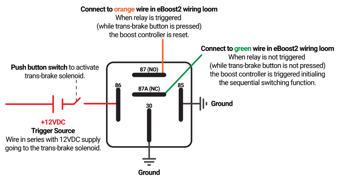
Electrical Schematic for Timed Switching Boost Control Applications (via using a 5-pin automotive relay)
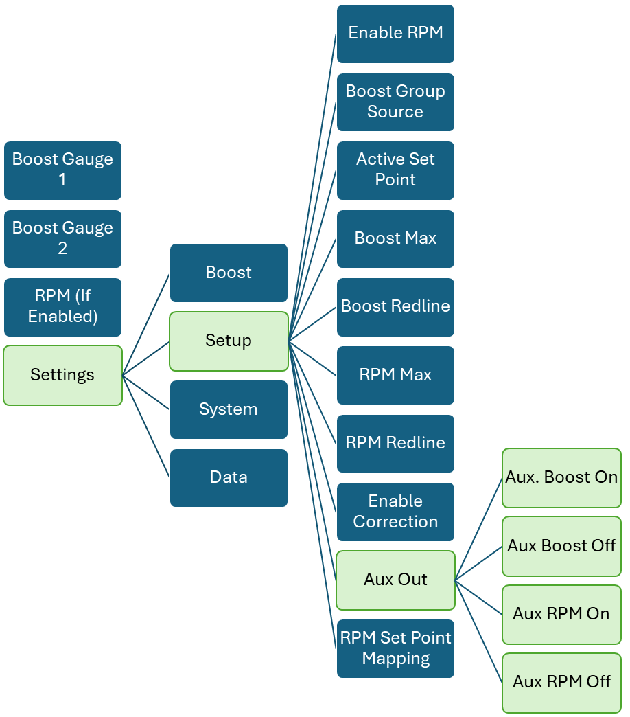
Auxiliary Output
The e-Boost3 has an auxiliary output function designed to control an auxiliary device once a certain boost pressure or RPM value is reached i.e. water spray, water injection, warning light or nitrous controller. This circuit can be used to control a resistor type automotive relay with a maximum current draw of 2 amps.
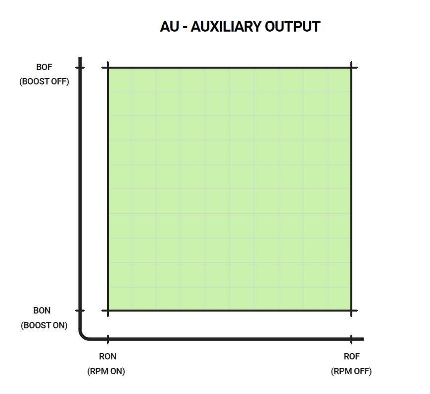
There are four options bOn, bOF, rOn and rOF. The boost setting on (bOn) and off (bOF) value will be entered in the units that are currently selected for display. Between the bOn and bOF values the auxiliary output circuit will be closed and therefore will switch the relay on. The RPM setting on (rOn), and off (rOF) are entered as RPM. Between the rOn and rOF values the auxiliary output circuit will be closed.
If the bOF or rOF is set to zero there will be no off and the circuit will remain closed until boost or RPM drops below the rOn or bOn value. If using a boost setting only to switch the relay the RPM parameter values should be set to zero to turn off or vice versa. If using the auxiliary circuit as a nitrous controller, you can enter all four user definable parameters bOn, bOF, rOn, and rOF. The auxiliary circuit will be closed when boost and RPM fall with the window created by these four parameters. That is when boost pressure is between bOn and bOF AND when RPM is between rOn and rOF.
Delayed Switching
This function is for use with set point switch logics ISP/ESP/SSA/SSB and is designed to create a delay between set point switching and activation. The time delay will be between when a subsequent set point is switched and when it actually changes i.e. the current set point will continue functioning until the time delay has elapsed. dS1 in boost group 1 applies to the time delay when switching to SP1, dS2 in boost group 2 applies to the time delay when switching to SP2 and so on. To use time delay between set point switching and activation, dS must be ON. In the SETUP Parameter Menu you can activate or deactivate this function. If this function is deactivated all menus relating to the time delay are hidden from the Boost Menu i.e. dS1 – dS6 in respective boost group. Once dS is activated in the SETUP Parameter Menu, you can enter the delay time in the Boost Group.
Note: Activating SSC/SSD and SSE also brings up the dS parameter in the boost group.
Boost correction
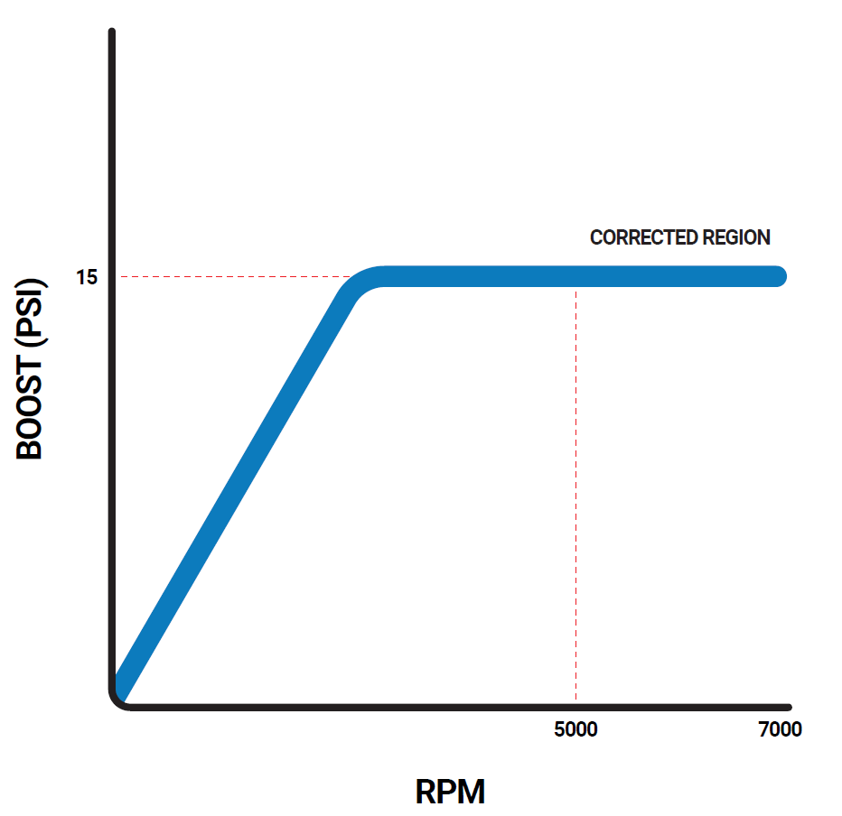
This function is use to reduce or eliminate boost drop off at high RPM. Switching this function on will display the boost correction menu in the boost group menu. This function is best performed on a chassis dyno where the graph of the boost curve can be displayed and accurately interpreted. More or less correction may be needed after review of the boost curve.
The boost correction function requires 3 parameters to work; the START RPM, the END RPM and the correction factor.
START RPM (RP1): This is the engine RPM at which boost begins to drop off.
END RPM (RP2): This is the engine RPM at which you want to turn off the boost correction function, normally set at redline.
Correction factor (FAC): The percentage at which boost is dropping off between the START and END RPM.
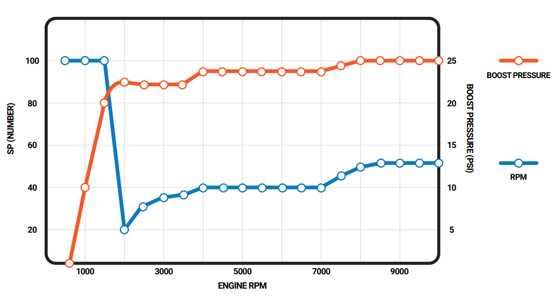
Example:
The following boost curve shows that between 5000 and 7000 RPM, the boost drops off from 15 PSI to 10 PSI.
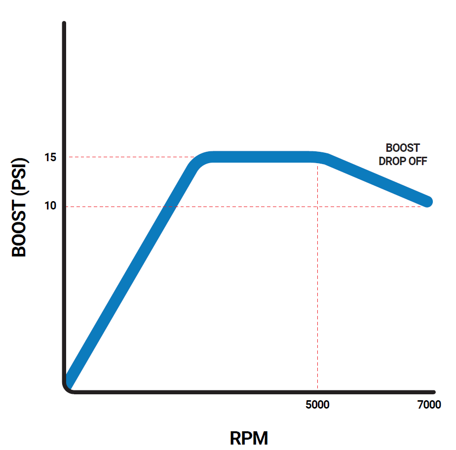
To reduce or eliminate this boost drop off, you need to input the following values:
RP1 = (5000 RPM)
RP2 = (7000 RPM)
FAC = 100 - [(Pressure End ÷ Pressure Start) X 100]
FAC = 100 - [(10 ÷ 15) X 100] = 33
RPM Based Set Point Mapping
This function allows you to map your boost curve against RPM. You can enter set point (SP) values against RPM values so you can tailor you boost curve. The RPM values are mapped in increments of 500 or 1000 RPM depending of the maximum RPM selected.
At each increment the desired offset which in turn gives you a boost pressure can be defined. When this function is turned on the RPM points 500, 1000, 1500, 2000 through to 19000, 19500, 20000 will appear in each boost group. Entering a value in the Boost Set Point (SP) parameter of the boost group will paste that value through all RPM points. This gives a starting point to adjust from.
When activating this function 3 options are available off, 10,000 and 20,000. Selecting 10,000 will give a max RPM of 10,000 with 500 RPM increments and selecting 20,000 will give a max RPM of 20000 and 1000 RPM increments. You could use this function to smooth out dips in your normal boost curve at certain RPM by enter higher set point values for these RPM.
Note this function is available for use with ISP, ESP and SSA-SSC. This function is cannot be turned on if SSD or SSE is on and if SSD or SSE is activated with rSP already then rSP will be turned off. RSP also cannot be used at the same time as COR (turning rSP on with COR already on will turn off COR).Gate pressure can be used with this function
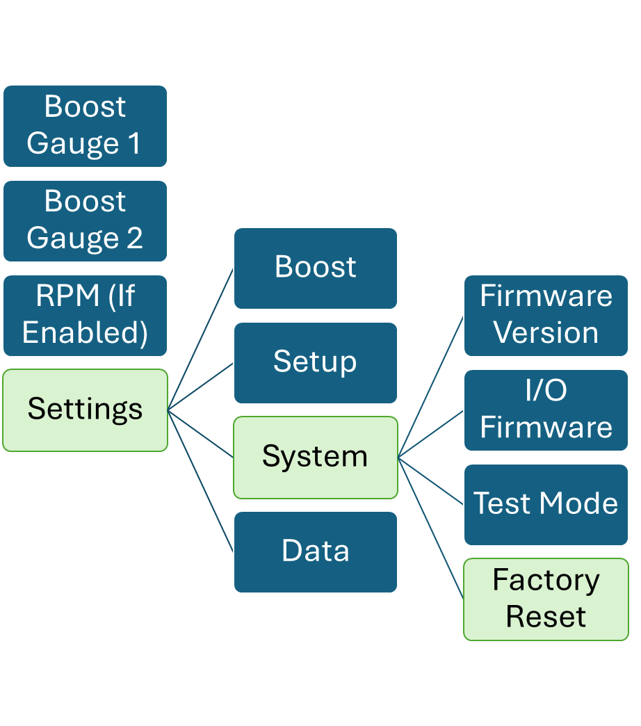
Service Menu
Fimware Number
The firmware number of your e-Boost3 unit can be displayed on the screen. This can be useful for technical support.
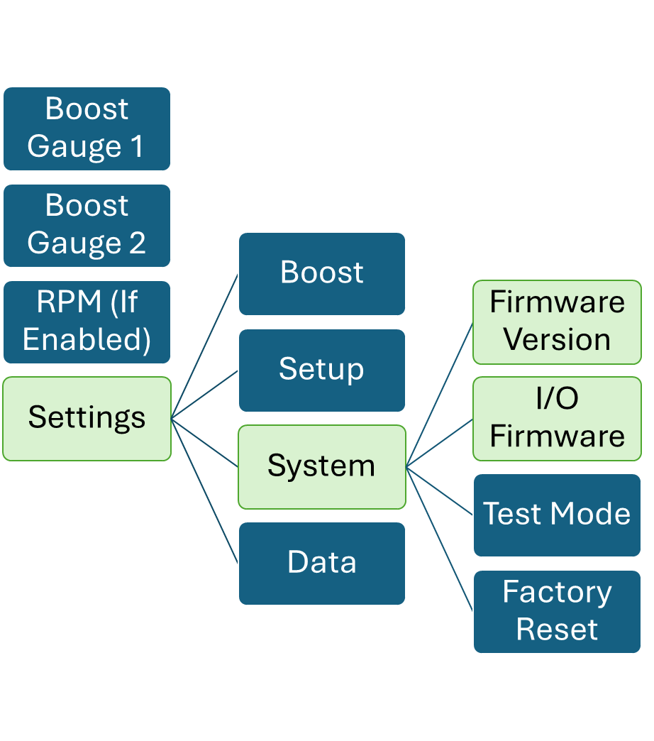
Solenoid Cycle
Test mode is able to cycle the PWM outputs from 0-100%, each output is phased 25% out from each other. Data can be viewed in the data tab. PWM will ramp up and down.
When power cycled the test mode state will turn off. And the unit will resume normal operation.
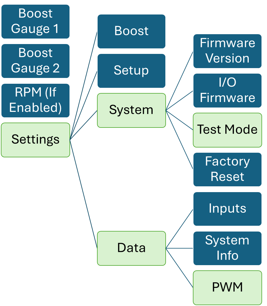
Reset
This function performs a factory reset and returns all the settings back to factory default.
Troubleshooting
The following points should be checked if you find that your engine is developing excessive boost, the boost pressure is fluctuating, or the desired boost level cannot be achieved. Please note the following checks will cure 99% of problems experienced when fitting a Turbosmart boost controller.
- Check wiring, check fused joints for blown fuses.
- Check that the boost controller is installed so that the arrow points toward the wastegate actuator.
- Check the joining hoses for splits, cracks or loose connections and are the correct size for the application.
- Check to see if the boost controller is blocked or contaminated with dirt or debris.
- Ensure that there is nothing but the boost controller in the hose between the pressure source and the wastegate actuator, ie tee pieces for boost gauge or to factory boost solenoid.
- Pressure test the wastegate actuator for leakage. The diaphragm or housing may be cracked or split.
- Check that the wastegate is operating correctly.