Vehicle Wiring Diagrams for eBoostUpdated 25 days ago
Vehicle Specific Wiring
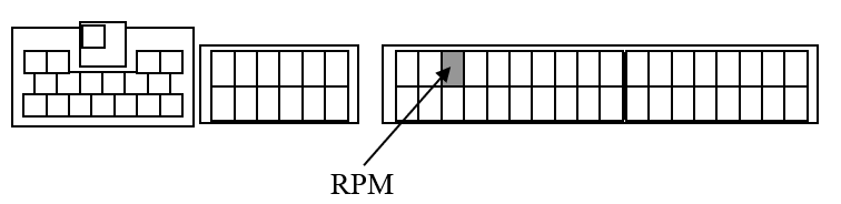
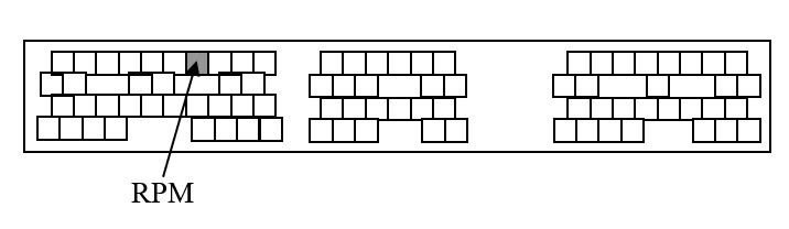
Following are vehicle specific ECU wiring diagrams for connecting the yellow RPM signal wire. Turbosmart recommends consulting an appropriately qualified technician for this installation. Be sure to count the number of pins and securely connect the yellow RPM wire to the appropriate ECU wire. Be sure to cover any exposed connections with electrical tape. Included with the kit are some resistors that can be added in line with the RPM signal to the head unit from the instrument cluster if the tachometer stops displaying RPM but the Eboost3 does display RPM. If 1 resistor does not fix the issue, add another resistor inline.
Location | Description |
A | Passenger Side Lower Dash (RHD) |
B | Left of the Glove Box |
C | Passenger Side Foot Rest (RHD) |
D | Behind the Glove Box |
E | Behind the Centre Console |
F | Under the Driver Seat (RHD) |
G | Under the Passenger Seat (RHD) |
H | Near the Steering Column |
I | Right of the Dash Cluster Panel |
J | Driver Side Lower Dash (RHD) |
K | Right of the Centre Console |
L | Engine Bay |
M | Front side of the Boot |
N | Back of the Driver Seat |
Toyota
Soarer JZZ30 1JZ-GTE 91.5 ~ Onwards
Ecu Location C
Supra JZA80 - 2JZ -GTE
ECU Location C
Supra JZA80 - 2JZ-GTE M/T ONLY
ECU Location C
Nissan
300ZX Z32 VG30DETT 89.7 ~ ONWARDS
SKYLINE R33 RB25DET 93.8 ~ 95.12
SKYLINE R32 RB20DET 89.5 ~ 93.7
200SX S14 SR20DET 93.10 ~ 96.5
SILVIA S13 CA18DET 88.5 ~ 91.1
180SX RS13 CA18DET 89.3 ~ 90.12
Ecu Location A
SKYLINE R34 RB26DETT 99.1 ~ ONWARDS
SKYLINE R33 RB26DETT 95.1 ~ 98.12
SKYLINE R32 RB26DETT 89.8 ~ 94.12
Ecu Location A
Note: Please add a 2k ohm resistor in line for RPM signal
SKYLINE R34 RB25DET 98.5 ~ ONWARDS
Ecu Location A
Note: Please add a 2k ohm resistor in line for RPM signal
SKYLINE R33 RB25DET 96.1 ~ 98.4
Ecu Location A
Note: Please add a 2k ohm resistor in line for RPM signal
SKYLINE R31 RB20ET 87.8 ~ 89.5
Note: Plead add a 2k ohm resistor in line for RPM signal
SILVIA S15 SR20DET 99.1 ~ ONWARDS
SILVIA S14 SR20DET 96.6 ~ 98.12
Ecu Location A
PULSAR GTIR N14 SR20DET 90.8 ~94.12
Ecu Location E
SILVIA PS13 SR20DET 91.1 ~ 93.9
180SX RPS13 SR20DET 91.1 ~ 96.7
Ecu Location A
180SX RPS13 SR20DET 96.8 ~ 98.12
Ecu Location A
Mitsubishi
GTO Z16A 6G72 90.10 ~ ONWARDS
Ecu Location E
LANCER CE9A 4G63 93.10 ~96.7 & CD9A 4G63 92.10 ~ 93.9
Ecu Location B
ECLIPSE D32A 4G63 95.6 ~ ONWARDS
LANCER CP9A 4G63 99.1 ~ ONWARDS
Ecu Location E
Note: For your rpm signal to work correctly with this ECU you may need to place a 3.3K ohm ¼ watt resistor (Colour code: orange, orange, orange, gold) in series with the yellow rpm input wire before connecting to the ECU.
LANCER CP9A 4G63 98.1 ~ 98.12
LANCER CN9A 4G63 96.8 ~ 97.12
Ecu Location B
Note: For your rpm signal to work correctly with this ECU you may need to place a 3.3K ohm ¼ watt resistor (Colour code: orange, orange, orange, gold) in series with the yellow rpm input wire before connecting to the ECU.
ECLIPSE D27A 4G63 89.11 ~ 95.6
Ecu Location E
Mazda
RX-7 FC3S 13B 88.9 ~91.11
ECU Location C
RX-7 FD3S 13B-REW 91.12 ~95.11
Ecu Location A
RX-7 FD3S 13B-REW 95.12 ~ONWARDS
Ecu Location A
RX-7 FC3S 13B 85.19 ~88.8
Ecu Location C
Subaru
LEGACY BC5 & BF5 EJ20G 89.2 ~ 93.9
Ecu Location C
IMPREZA GC8 EJ207 & GF8 EJ205 98.9 ~ ONWARDS
Ecu Location C
Note: For your signal to work correctly with this ECU you will need to place a 2K ohm ¼ watt resistor (Colour code: red, black, red, gold) in series with the yellow rpm input wire before connecting to the ECU.
IMPREZA GC8 & GF8 EJ20K 96.9 ~ 98.8
Ecu Location C
LEGACY BD5 & BG5 EJ20H 93.10 ~ 96.5
Ecu Location C
LEGACY BD5 & BG5 EJ20H A/T 96.6 ~ 98.5
Ecu Location C
IMPREZA WRX 2002
Ecu Location C
LIBERTY B4
Ecu Location C
STI 01-02
Ecu Location C
STI 03-04
Ecu Location C