TS-XXXX-XXXX Pressure Bypass ControllerUpdated 3 months ago
Product Name: | Pressure Bypass Controller |
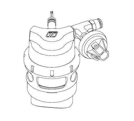
Product Description: | TS-XXXX-XXXX Pressure Bypass Controller |
Product Number: |
TS-XXXX-XXXX
|
 Important notes on your Pressure Bypass Controller
Important notes on your Pressure Bypass Controller
- Please thoroughly read and understand these instructions before commencing this installation.
 Recommendations
Recommendations
- Turbosmart
recommends that your BOV controller is fitted and adjusted by an appropriately
qualified technician
- Turbosmart recommends that a boost gauge be permanently fitted to the vehicle
 Kit Contents
Kit Contents
Quantity | Description | Use |
1 | BOV Controller Unit | BOV Controller |
1 | Race Port assembly | Blow off valve fitted with orange inner spring and stainless steel weld flange |
1 | Loom | Electronic Loom |
1 | Pneumatic Quick Connect | TS-0550-3053 |
1 | Nylon Tubing 1/4" | TS-0550-3056 |
Tools Required
Tools Required
- Non-marking spanners to tighten fittings
- 4mm hex key
-
Flat Blade screwdriver
Suggested Sealant
Suggested Sealant
- Loctite 567 Thread Sealant
Functionality
The Pressure Bypass Controller works by waiting for a switched input to activate the activation of the Pressure Bypass Controller, It then energises the solenoid to vent all of the air out of the BOV
cap, causing a pressure differential between the piston of the BOV and the cap
which will vent pressure from the intake system. There are 2 parameters that
can be adjusted to tune the controller for optimum performance; duration and sensitivity. The green LED shows that the BOV controller is on. The yellow LED
shows when the solenoid is activated.
Installation
Mount
the unit away from any heat source and moisture. Wire up the unit as per
diagram. Do not connect the unit to a power supply which will have a greater
voltage than 14V DC. Unused
wires must be insulated with electrical tape so that they do not touch other
wires or the chassis.
Pin | Description | Colour |
Pin 1 | N/A | N/A |
| Pin 2 | Hobbs Switch 0V | Green |
Pin 3 | Hobbs Switch Input | White |
Pin 4 | Solenoid Trigger Signal | Yellow |
Pin 5 | N/A | N/A |
Pin 6 | N/A | N/A |
Pin 7 | Controller Ground (GND) | Black |
Pin 8 | Controller Power (12V) | Red |
Solenoid Connection
Electrical connection
Connect
one wire of the solenoid to a fused ignition activated 12V power source and connect the other
wire to the Solenoid trigger signal (Yellow) on the BOV controller unit.
Polarity is not important.
Adjusting your Pressure Bypass Controller
DURATION: The duration is the
length of time that the solenoid blocks the pressure signal to the BOV. The
longer the duration, the longer the BOV will not have pressure supplied to the
cap, essentially keeping the BOV open.
SENSITIVITY: The sensitivity setting
determines how the Pressure Bypass controller reacts to throttle movement. The controller
will only activate on negative changes in throttle. The higher the sensitivity
setting, the lower the negative change in throttle movement needs to be before
the solenoid will activate the BOV e.g. a change from 4V to 3.5V will not
activate the valve but from 4V to 3V will activate the valve.
Notes
Sensitivity adjustment will have no feedback due to the switch condition being open and closed.