TS-0311-100X - eBoost 3 External SensorUpdated 25 days ago
Important Notes on Your New eBoost 3 with External Sensor
- Turbosmart recommends that your e-Boost3 is fitted by an appropriately qualified technician.
- Consult your local tuning specialist before setting your boost pressure, setting boost beyond your engines capability can result in severe engine damage or failure!
- Turbosmart recommends that the engines Air/Fuel ratio is checked once the desired boost pressure is set, any increase in boost pressure can cause the engine to run lean resulting in severe engine damage or failure.
- Turbosmart recommends that the e-Boost3 is not used in conjunction with any type of “Draw Through” Fuel System.
- Turbosmart recommends that boost pressure is set using a Dynamometer and not on public roads.
- The e-Boost3 may not be able to completely compensate for a drop in boost pressure at high RPM due to the turbocharger operating beyond its maximum efficiency range i.e. incorrect turbocharger sizing or excessive exhaust backpressure.
- The e-Boost3 cannot compensate for increases in boost pressure at high RPM due to inadequate waste gate flow capacity; the turbo system must maintain a steady base boost curve.
- The e-Boost3 cannot be used with external wastegates that are in a poor, worn or non-serviceable condition.
- For best results your turbocharger should be correctly sized for your application.
- A Turbosmart Fuel Cut Defender may need to be used in conjunction with your e-Boost3, Please check out our website at Turbosmart.com or your nearest Authorised Turbosmart Dealer for more information on Fuel Cut Defenders.
- Erratic operation of electronic parts can be caused by Electro Magnetic Interference (EMI). EMI can be generated by aftermarket ignition systems such as CDI which, if wired incorrectly, generate large amounts of EMI through the vehicles electrical system. This can cause items such as ECU’s and boost controllers to be affected. Please follow ignition system installation instructions VERY carefully to avoid EMI affecting the e-Boost.
- eBoost 2 and eBoost 3 values are not interchangeable. reviewing boost control settings should be taken to ensure operation is similar. eB3 should be setup as a new unit.
Recommendations
- Turbosmart recommends that the Air Fuel ratio is checked once boost pressure is set
- Turbosmart recommends that an accurate boost gauge be permanently fitted to the vehicle
- Turbosmart recommends that your boost controller is fitted and adjusted by an appropriately qualified technician
Tools Required
- General Mechanic Tools
- General Electrical Tools
________________________________________
Installation
Mounting the eBoost 3
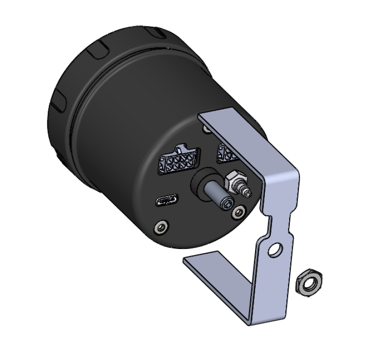
- The e-Boost3 is not waterproof and must be mounted inside the cabin. The unit has an operating temperature range of -20degC to +70degC.
- The e-Boost3 is designed to be panel mounted with the bracket supplied. Alternatively the 60mm e-Boost3 can be mounted using the Turbosmart 60mm dash mounting accessory, pod or “A pillar” mounts. The Turbosmart dash mounting accessory offers full tilt and swivel adjustment.
• The E-Boost 3 requires a vacuum/pressure signal from the intake manifold to function. A combination of poly tube and silicone hose is used to connect the E-boost 3 to a adequate vacuum/pressure signal. Route the poly tube from the E-boost 3 head unit through the fire wall approximately 100mm (4”) only as the poly tube is not rated to the high temperatures of the engine bay.
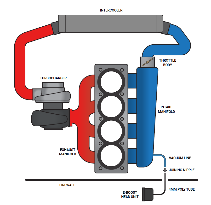
- Use the connecting barb to join the poly tube to the 3mm ID silicon hose at the firewall/bulkhead. Ensure the poly tube is pressed all the way onto the connecting barb
- Route the silicon hose through the engine bay and connect it to a pressure/vacuum signal from the inlet manifold. Use the supplied tee piece if necessary.
- Secure all connections with the supplied hose clamps
Wiring the eBoost 3
- The e-Boost3 must be connected to a typical automotive 12 volt negative earth electrical system.
- Soldering or Crimp on electrical connectors must be used on all electrical connections
- Unused wires must be insulated with electrical heat shrink or electrical tape so that they do not touch other wires or the chassis
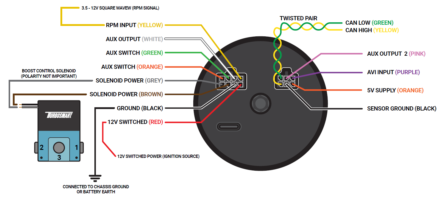
- Refer to the following table and diagram for detail on wiring the e-Boost3.
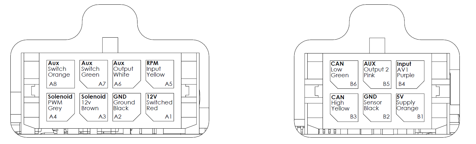
Viewed from back of eBoost.
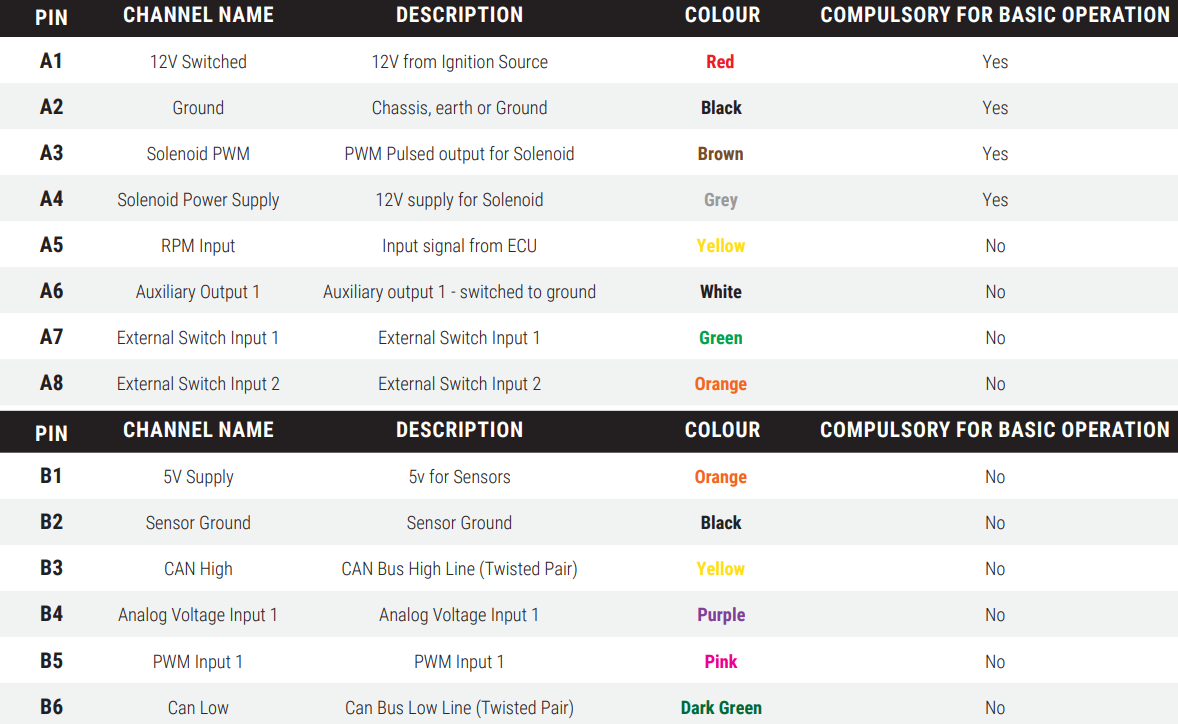
Generic Pinout
EXTERNAL PRESSURE CONNECTION
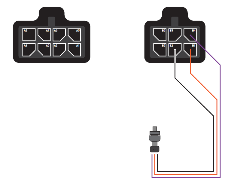
Utilising a 5V, Sensor Ground and Analog Input we can wire in a pressure sensor as part of the external pressure control.
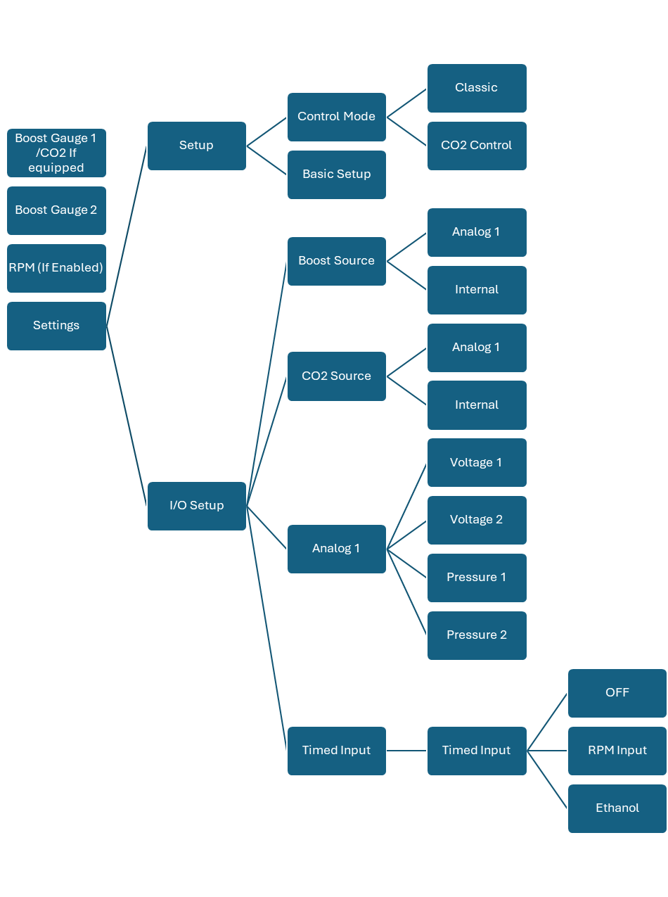
External Pressure Sensor Control
To use the external pressure sensor the Boost Source must be changed from internal to analog 1. This will use the Analog 1 Sensor for boost control. Analog 1 setting must be setup to use the voltage and pressure values for the sensor. The internal pressure sensor is rated to 40psi
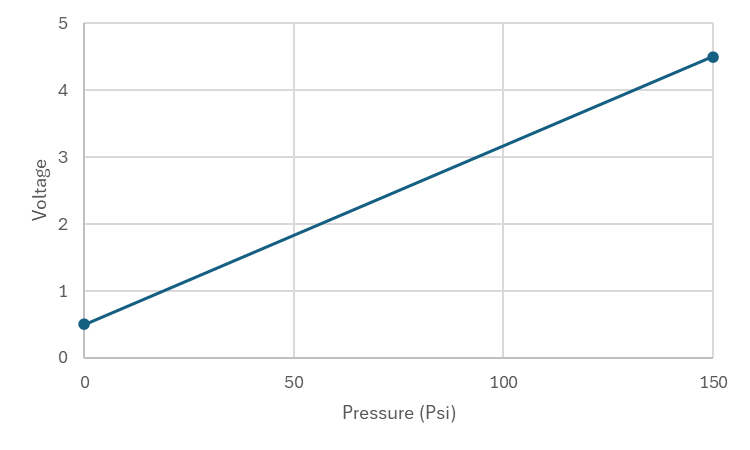
Example Typical 150psi Sensor
In this case, the sensor has to be inputted as below.
| Voltage 1 | 0.5 |
| Voltage 2 | 4.5 |
| Pressure 1 | 0 |
| Pressure 2 | 150 |