CO2 - WG60 Diaphragm ReplacementUpdated 25 days ago
How to Change Your GENV 60mm Wastegate Diaphragm
- 98mm (WG60): TS-0550-3061
CAUTION! Ensure diaphragm is contained within the groove prior to cap re-assembly.
Pay attention not to rotate diaphragm.
Remove Wastegate from Manifold
Remove boost pressure source hose from the wastegate as well as the breather hose is fitted. Unscrew outlet V-Band nut in a anti-clockwise direction to the very end of the thread, Squeeze the nut against the V-Band in a syringe like motion to expand the V-band over the flange. Repeat for inlet V-Band. Remove GenV wastegate being careful not to lose the valve seat. Mark the orientation of the valve to the body with tape or a paint pen.
CAUTION! Allow engine to cool down before removing your GenV wastegate.
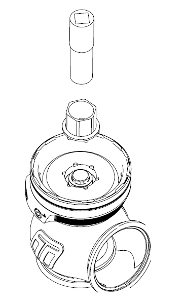
Remove Top Cap
Prior to removing the GenV wastegate cap, remove all fittings from the 1/8”NPT ports. Press down on the cap in a press or vice. Unscrew locking collar with the large end of the provided collar tool in an anti-clockwise direction until completely disengaged and slowly remove tension from the press or vice allowing the spring to expand, finally remove cap when the spring has stopped expanding.
CAUTION! Use soft jaws to prevent damage.


Diaphragm Replacement
Use the supplied tool in the diaphragm replacement kit, engage the diaphragm aligning the splines and grooves. Use a 25mm spanner on the tool to prevent the diaphragm from spinning. Use a 12 point 14mm socket through the centre of this tool onto the valve retaining cap. Undo the valve retaining cap by rotating anti clockwise.

Remove the valve retaining cap and spring washer, Sit the wastegate on down so that the valve is elevated and supported. Using a small flat blade screwdriver to pry one edge of the split in the valve circlip out and up, work your way around the circlip until it is removed. Take note of the orientation of the diaphragm, lift the old diaphragm over the valve and discard. Use this opportunity to thoroughly clean the wastegate removing any dirt from the actuator, ensure the diaphragm groove is free of debris and fit your replacement diaphragm over the valve.

Sit the new valve circlip on top of the valve ensuring it is concentric, Use the valve retaining cap on top of the circlip to lightly press the new circlip over the valve into place, Confirm the circlip is located correctly in the circlip groove of the valve, adjust if necessary. Let the valve drop down into the diaphragm, sit the new spring washer onto the nipple of the valve with the outside of the cone away from the valve. The locking tab can then be placed on the diaphragm support.
There are 4 tabs that must be aligned correctly, noted in Red. It's important that these are located correctly as the valve retaining cap must correctly locate all the way onto the diaphragm support.

Apply a dab of high temperature thread locker/sealer like Resbond to the lower threads of the valve retaining cap and screw into the diaphragm support. Support the diaphragm with the supplied tool and tighten the valve retaining cap to 25N.m (19ft/lbs)


Align the valve orientation marks and confirm the diaphragm bead is seated in the groove of the actuator. Install desired spring combination. Configure Wastegate with preferred spring combination of inner, middle and outer springs
Once torqued, the wings of the locking tab must be bent upwards to ensure locking of the valve retaining cap.
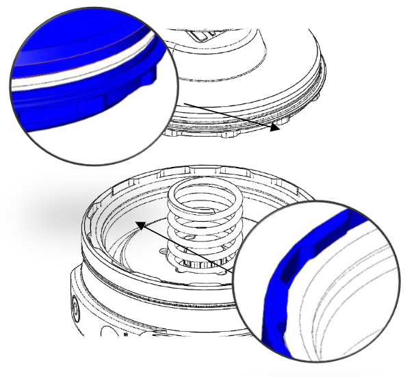
Familiarise Yourself with Cap and Body Notches
Locate cap and body notches and grooves which dictate the alignment of the cap. These notches are used to locate the cap onto the body and must be aligned prior to compression of the cap onto the body.
CAUTION!
Ensure notches are aligned and seated home correctly prior to exerting force to tighten collar, permanent damage will occur if these are not aligned correctly.
Press cap onto body
Using a press or vice, compress the cap onto the body ensuring the notches are remaining aligned. Once the cap has seated home onto the bod, screw the collar down by hand in a clockwise direction. While still in the press or vice, Tighten the collar further with the collar tool until the collar will not turn.
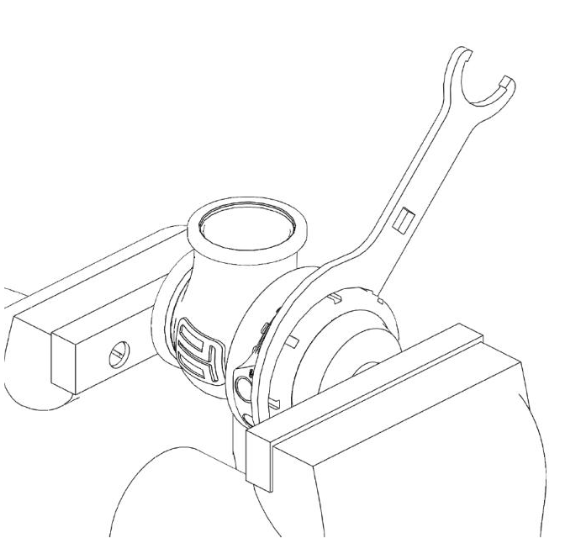
CAUTION! Maintain downward pressure on cap while tightening collar or non-repairable thread damage will occur.
Reinstall fittings to the cap of the wastegate using fresh sealant.
Reinstall GenV wastegate
Place v-band over weld on flange by unscrewing the nut on the v-band as far out as possible and then squeezing the bolt in a syringe motion to expand the v-band (squeeze the dots together below). Once the v-band is in its fully expanded position, slide the v-band over the flange to allow for the wastegate to be installed. Do not forget to put the valve seat into the body before mounting the unit on the exhaust manifold. Using the 3/8” deep socket and a torque wrench Tighten the V-Band to 7N.m (5 ft/lbs).